


CARF Rebel MAX - Build Thread


 12-15-2021, 10:11 PM
#77

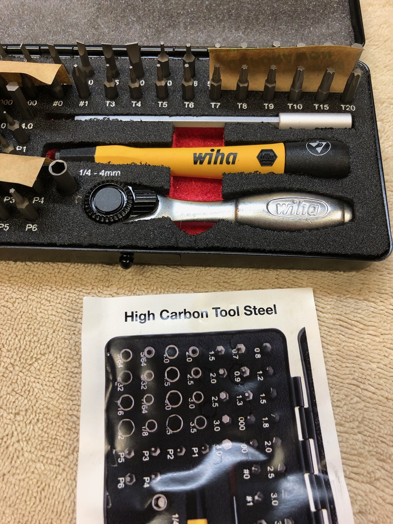
Super, I’ve sold a good number of those sets and they are great. Sometimes the handle will be a little bulky to get into tight areas.
The ‘knitter’ has a good eye for quality though 🙂
I would still get a set of quality L keys.
The ‘knitter’ has a good eye for quality though 🙂
I would still get a set of quality L keys.
The following users liked this post:
AEROSHELDON (12-16-2021)
12-17-2021, 06:44 AM
#80
Thread Starter
My Feedback: (1)

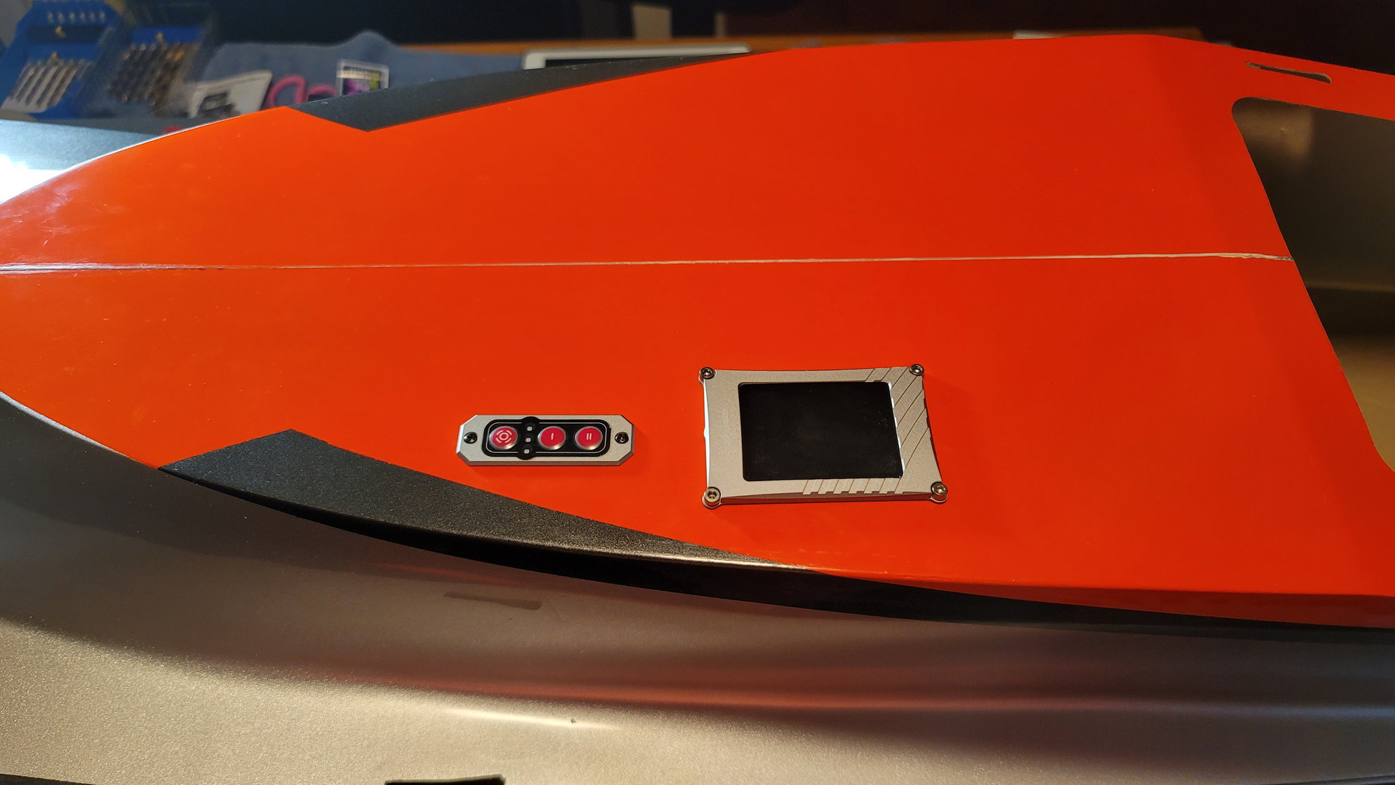
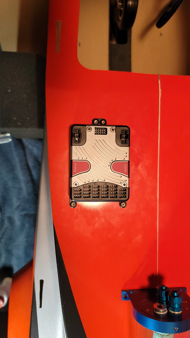
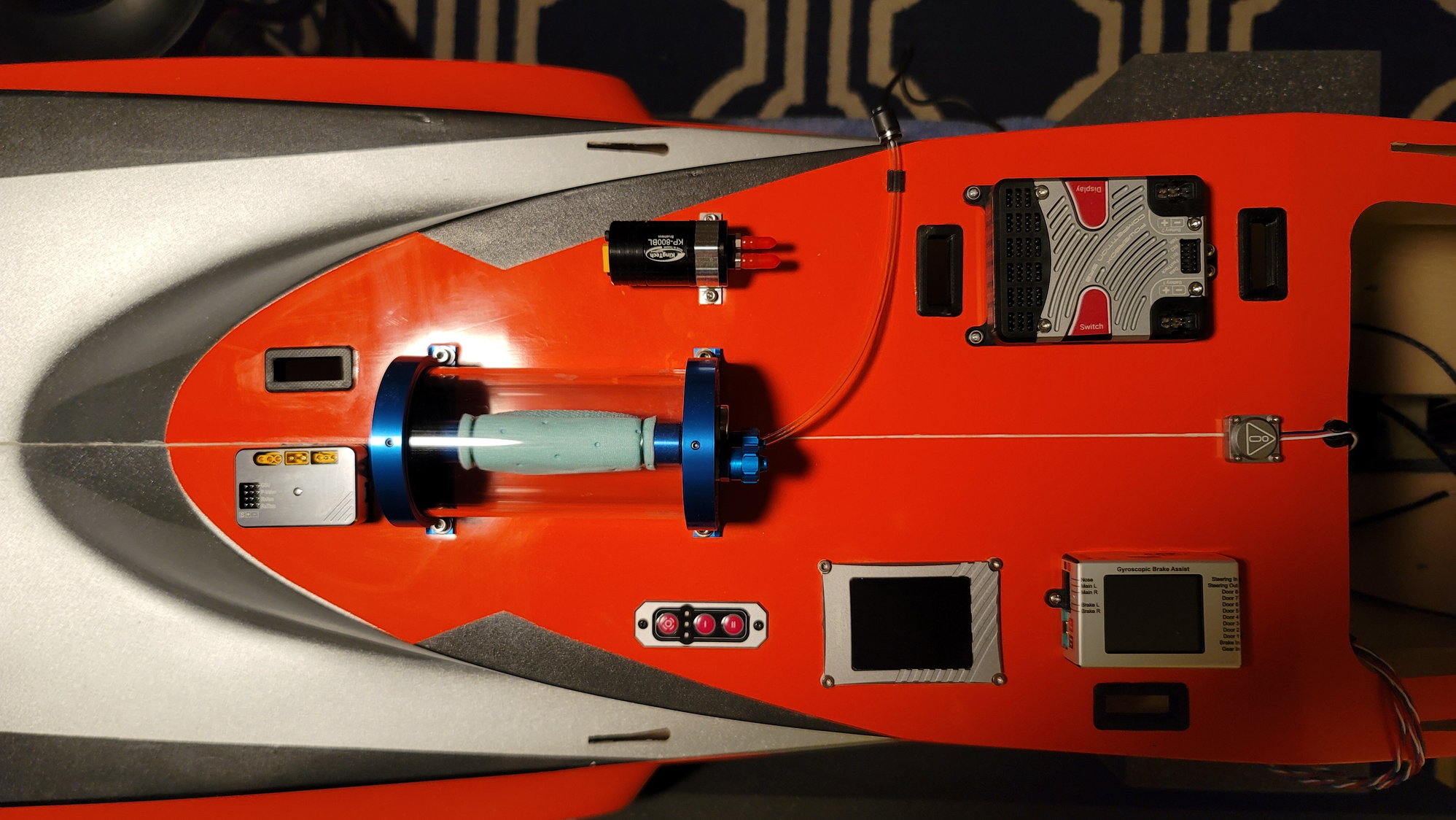
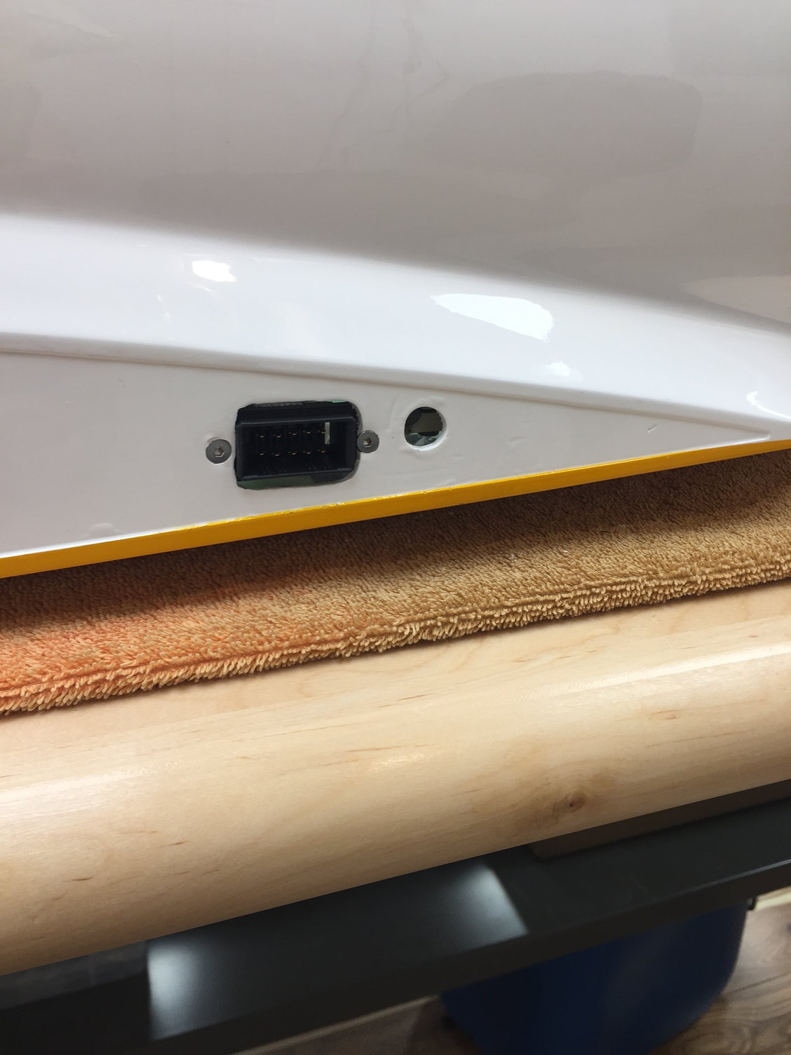
I started working on avionics this week and finding where I wanted items placed on the massive "deck" (under the canopy) of the Rebel Max. I also received my PowerBox Competition SR2 on Wednesday as I definitely needed this to figure out where things went. With the SR2, the display unit and switch don't mount flush and a hole has to be cut or some sort of mounting frame needs to be made. Hint - One of you awesome 3D Printer people should come up with a mounting frame for the PowerBox equipment. They do have them for their batteries but not anything else. Because of this, I had to cut a hole for the TFT Screen in the deck where I wanted it mounted. It's not a huge hole but a decent-sized one none-the-less. They do provide a small template which helps. I'm hoping to complete the arrangement and mounting of all the equipment this weekend but I did mount the TFT screen last night.
A few words of caution: The two fuse halves are bonded together with a layer of carbon fiber cloth that runs the length of the fuse right at the seam. This is good. When cutting holes, I, personally, wouldn't cut through the carbon fiber so place your equipment accordingly. The second thing is that the fuse is about 1/8" thick but this is not all fiberglass. Under the fiberglass is a type of foam or substructure that doesn't offer a lot of strength. Make sure to put little blocks of maybe 1/8" ply under the deck where you're going to screw things into it so that the screws have something to bite into.
For the TFT screen, I used the template provided to cut a square with a 1/2" border around the screen in 1/8" plywood and used a my scroll saw to cut out the shape of the screen. That will mount under the deck and around the hole I cut in the deck for the screen. Use a Dremel cutoff wheel to cut into the deck and then a sanding drum to get the hole perfect near the edges. This will work well for any cutting you need to do but, the majority of equipment will simply need holes drilled for mounting screws and then the little 1/8" pieces of plywood you make as backers will give the screws some bite. Canadian Man said to me to screw anything that can be screwed and use 3M double-sided tape or Velcro for the very light things that you cannot screw down i.e. RX, turbine display, etc.
I'll post more pictures after I get the deck finished this weekend
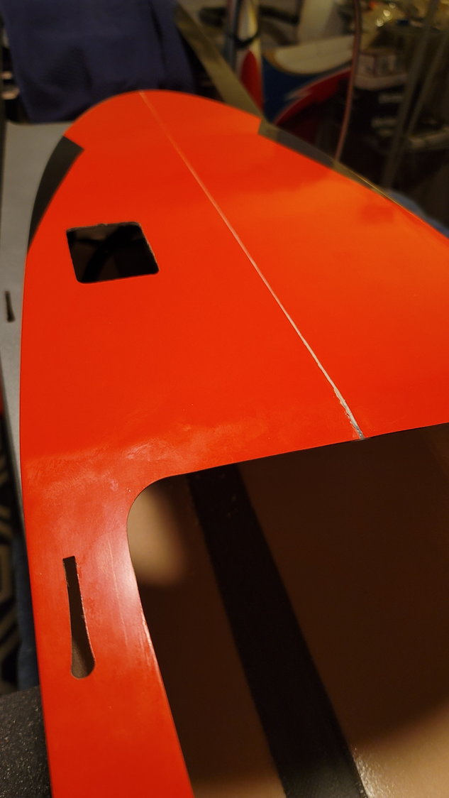
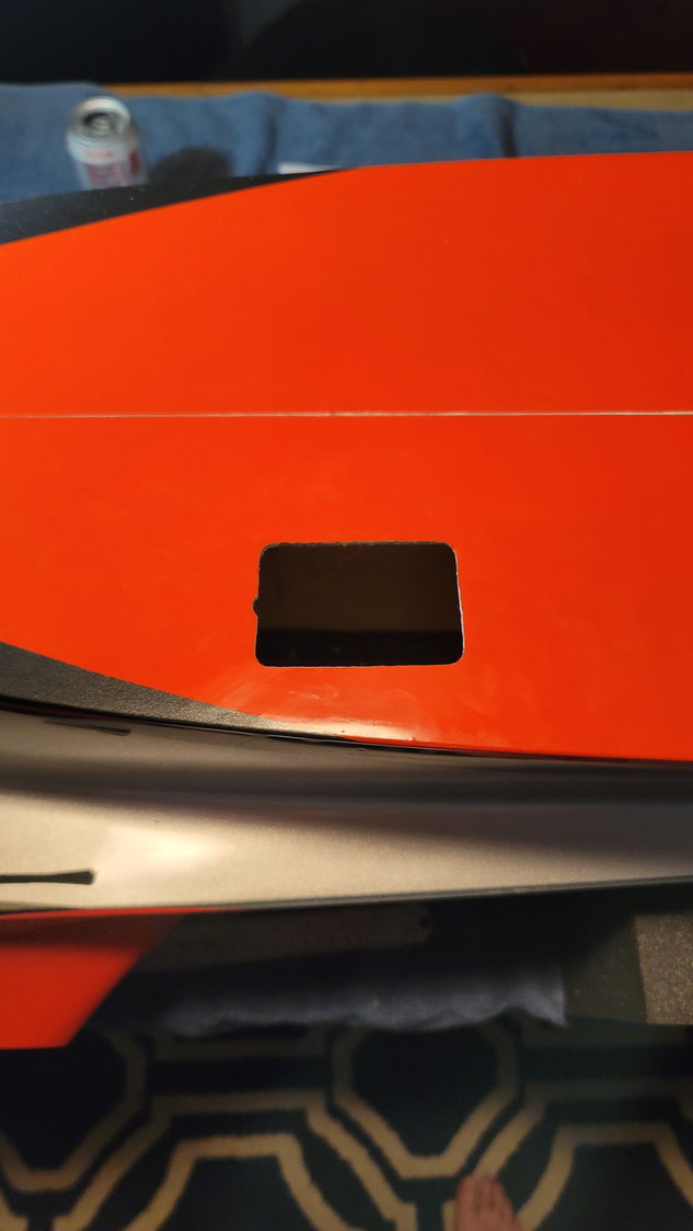
Fuse is 1/8" thick but you still need plywood backs underneath any screws
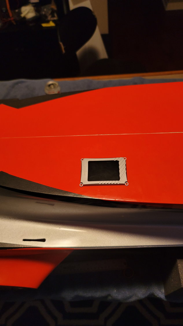
Screen perfectly fits in the hole I cut with the template.
A few words of caution: The two fuse halves are bonded together with a layer of carbon fiber cloth that runs the length of the fuse right at the seam. This is good. When cutting holes, I, personally, wouldn't cut through the carbon fiber so place your equipment accordingly. The second thing is that the fuse is about 1/8" thick but this is not all fiberglass. Under the fiberglass is a type of foam or substructure that doesn't offer a lot of strength. Make sure to put little blocks of maybe 1/8" ply under the deck where you're going to screw things into it so that the screws have something to bite into.
For the TFT screen, I used the template provided to cut a square with a 1/2" border around the screen in 1/8" plywood and used a my scroll saw to cut out the shape of the screen. That will mount under the deck and around the hole I cut in the deck for the screen. Use a Dremel cutoff wheel to cut into the deck and then a sanding drum to get the hole perfect near the edges. This will work well for any cutting you need to do but, the majority of equipment will simply need holes drilled for mounting screws and then the little 1/8" pieces of plywood you make as backers will give the screws some bite. Canadian Man said to me to screw anything that can be screwed and use 3M double-sided tape or Velcro for the very light things that you cannot screw down i.e. RX, turbine display, etc.
I'll post more pictures after I get the deck finished this weekend
Fuse is 1/8" thick but you still need plywood backs underneath any screws
Screen perfectly fits in the hole I cut with the template.
Last edited by smcharg; 12-17-2021 at 08:02 AM.
12-17-2021, 02:14 PM
#81

Looking great Scott! The Max is definitely the next one on my list! I have 20 flights on the Pro now and I think it�s the most I�ve enjoyed Rc Jet flying, it�s so easy to fly and make you feel so confident to try new maneuvers. It�s my every Sunday flyer now.
The following users liked this post:
smcharg (12-18-2021)
12-17-2021, 02:23 PM
#82
Senior Member
This is from the Rebel Pro Manual to use plywood underneath the area for the electrons mounting.
It's on page 2 highlighted won't add too much weight but will help reinforce the fuselage from twisting.
It's on page 2 highlighted won't add too much weight but will help reinforce the fuselage from twisting.
Last edited by Skunkwrks; 12-17-2021 at 02:26 PM.
12-18-2021, 09:11 AM
#83
Thread Starter
My Feedback: (1)
I’m definitely putting plywood in there. I just haven’t decided on little scraps or a small 1/8” sheet going side to side. The tank former is 410mm back from the front lip of the deck so that will help in placing stuff. I’m going to try to have all equipment mounted today.
12-18-2021, 10:37 AM
#84
Senior Member
Scott, when I get my Pro, I will use 1/8 aircraft quality plywood with 9462 hysol to support the upper tray. If I gain 2-3 oz, the benefit of stiffness infuse is worth it to me
Is there enough space to place your UAT tank near the fuel tank and turbine? It keeps things a lot simpler.
Is there enough space to place your UAT tank near the fuel tank and turbine? It keeps things a lot simpler.
12-20-2021, 05:57 AM
#85
Thread Starter
My Feedback: (1)
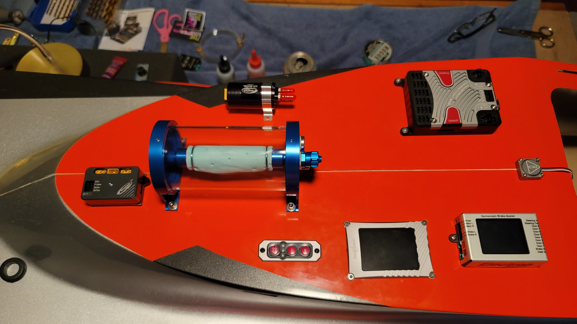
This weekend was pretty productive. Not a lot to say but several pictures to follow. After the preceding discussion, I did go ahead and line the majority of the top deck's underside with 1/8" lite ply. I used 30-minute epoxy to bind. Under the 250ml UAT, I placed 1/4" lite ply. That is the heaviest component and wanted some extra strength. This was a small piece just slightly bigger than the UAT, itself. Once this was all finished, the top deck was...pardon the pun....stiff as a board with almost no flex.
The piece of ply you see here is just to keep the top deck from getting scratched while the 30-minute epoxy dried.
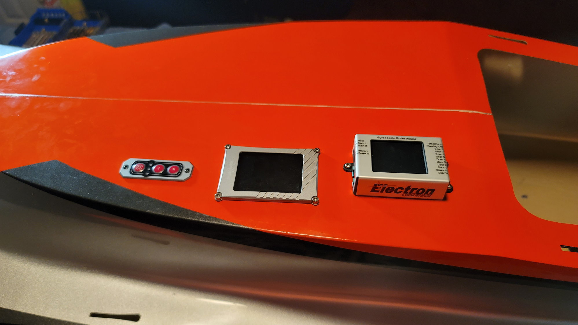
Two holes, aside from those that will need to be cut for wires, had to be cut out. One was discussed in the previous post and the other was for the PowerBox Compeition SR2 switch. All other components were aligned and measured against the seam of the aircraft and screwed down to the deck. There were only two components that did not get screwed down; the ECU/DRM for the turbine and the iGyro SAT. Both of these were mounted with double-sided tape (the SAT came with it and the ECU/DRM I used 3M double-sided tape with a foam pad). I'm very happy with the results.
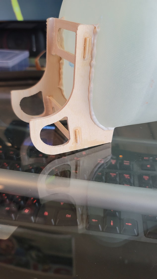
The last thing I wanted to point out was some little fuel line keepers and a wire keeper. These are made by Canadian Man and "The Lighter Side of R/C". He sells the fuel line keepers in at least 3 sizes; 3-4mm, 6mm, and 8mm. They are 3D printed and I attached them to the top deck with "Amazing Goop Max". I've also purchased some fuel valve holders that even come with a little template for drilling and some rectangular 3D printed "grommets" to run the wires up to the PowerBox and power lines. I'll post pictures of them when they are received and installed. Jonathan's website is https://www.thelightersideofrc.com/
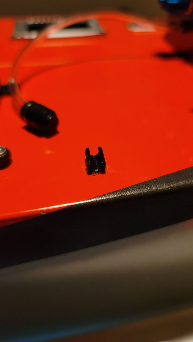
Once the goop dries, this will hold a 4mm fuel line with a cap on the end (seen above the part). This will be my fill line.
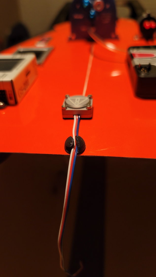
The wire keeper is holding the iGyro SAT wire which will run under the deck and up to the Competition SR2
I've also assembled my wire harness that runs from the Competition SR2 to the aft fuse for the Elevators and Rudder servos. I used my regular wire keepers (shown at the beginning of this thread) and ran them down the right side and under the canopy lip. While waiting for the 3D printed parts to show up, I'm going to assemble the 5L fuel tank and get that installed.
The piece of ply you see here is just to keep the top deck from getting scratched while the 30-minute epoxy dried.
Two holes, aside from those that will need to be cut for wires, had to be cut out. One was discussed in the previous post and the other was for the PowerBox Compeition SR2 switch. All other components were aligned and measured against the seam of the aircraft and screwed down to the deck. There were only two components that did not get screwed down; the ECU/DRM for the turbine and the iGyro SAT. Both of these were mounted with double-sided tape (the SAT came with it and the ECU/DRM I used 3M double-sided tape with a foam pad). I'm very happy with the results.
The last thing I wanted to point out was some little fuel line keepers and a wire keeper. These are made by Canadian Man and "The Lighter Side of R/C". He sells the fuel line keepers in at least 3 sizes; 3-4mm, 6mm, and 8mm. They are 3D printed and I attached them to the top deck with "Amazing Goop Max". I've also purchased some fuel valve holders that even come with a little template for drilling and some rectangular 3D printed "grommets" to run the wires up to the PowerBox and power lines. I'll post pictures of them when they are received and installed. Jonathan's website is https://www.thelightersideofrc.com/
Once the goop dries, this will hold a 4mm fuel line with a cap on the end (seen above the part). This will be my fill line.
The wire keeper is holding the iGyro SAT wire which will run under the deck and up to the Competition SR2
I've also assembled my wire harness that runs from the Competition SR2 to the aft fuse for the Elevators and Rudder servos. I used my regular wire keepers (shown at the beginning of this thread) and ran them down the right side and under the canopy lip. While waiting for the 3D printed parts to show up, I'm going to assemble the 5L fuel tank and get that installed.
The following users liked this post:
Canadian Man (12-20-2021)
12-20-2021, 09:59 AM
#86
Senior Member
Scott the reinforced top deck looks great, with all the electronics and the tank looks very clean and professional. Seems Jonathan has got you hooked up with the 3D parts we use in our planes they are very handy and has guided you on installation. Again great job Scott.
12-20-2021, 10:11 AM
#87
Thread Starter
My Feedback: (1)
Scott the reinforced top deck looks great, with all the electronics and the tank looks very clean and professional. Seems Jonathan has got you hooked up with the 3D parts we use in our planes they are very handy and has guided you on installation. Again great job Scott.

Concerning distance....I did spend some time on the phone with Dirk at PRCJ / Kingtech yesterday and he said distance for these things is not a problem. He said he had a test system with many feet between the turbine and tank and never once had an issue. So, yes, it could be done but I think this setup will work wonderfully and I've seen a few others done this same way including Andreas' Max on the CARF website.
Last edited by smcharg; 12-20-2021 at 04:44 PM.
The following users liked this post:
Canadian Man (12-20-2021)
12-20-2021, 10:38 AM
#88
Senior Member
Thanks. I meant to address your other comment concerning placement of the UAT. I did consider putting it down in the "basement" but I do want to actually keep it in front of the CG as much as reasonable without too much distance in the Tank - UAT - Pump series. Since the 5L fuel tank has to be taken out forward due to the way the tank is assembled and bolted into the former, I can't really put it in front of the tank as it would make it difficult to pull out should I ever need to. I have moved it somewhat forward as it now sits in front of the tank "bulkhead" instead of straddling it on the top deck. Plus, I spent $250 for this nice UAT and want to show it off a little
Concerning distance....I did spend some time on the phone with Dirk at PRCJ / Kingtech yesterday and he said distance for these things is not a problem. He said he had a test system with many feet between the turbine and tank and never once had an issue. So, yes, it could be done but I think this setup will work wonderfully and I've seen a few others done this same way including Andreas' Max on the CARF website.
Concerning distance....I did spend some time on the phone with Dirk at PRCJ / Kingtech yesterday and he said distance for these things is not a problem. He said he had a test system with many feet between the turbine and tank and never once had an issue. So, yes, it could be done but I think this setup will work wonderfully and I've seen a few others done this same way including Andreas' Max on the CARF website.
The length of piping is too much concern those pumps fill the lines very quickly and if the Boss Andreas of Carf has done this on the companies, Max Rebel, then its good to follow his example.
The following users liked this post:
Canadian Man (12-20-2021)
The following users liked this post:
Skunkwrks (12-20-2021)
 12-24-2021, 12:38 PM
#92
Thread Starter
My Feedback: (1)
We can see the finish line, folks.
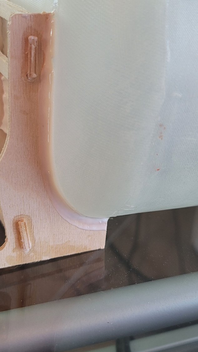
I thought I'd give a couple updates while I'm letting Hysol dry on the rear tank brace.
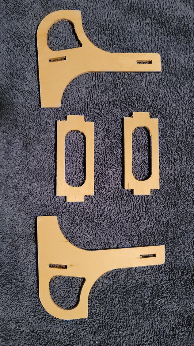
These are the 4 pieces that you need to assemble the rear tank brace. They fit very nicely together with no sanding needed.
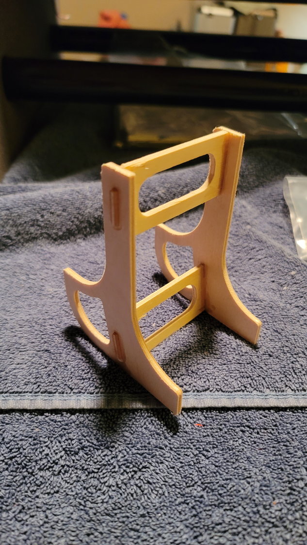
The pieces assembled. I glued this together with medium CA and then went back and Hysol'd key areas. The cradle facing away is the part that sits under the wing tube. The cradle facing us is for the tank
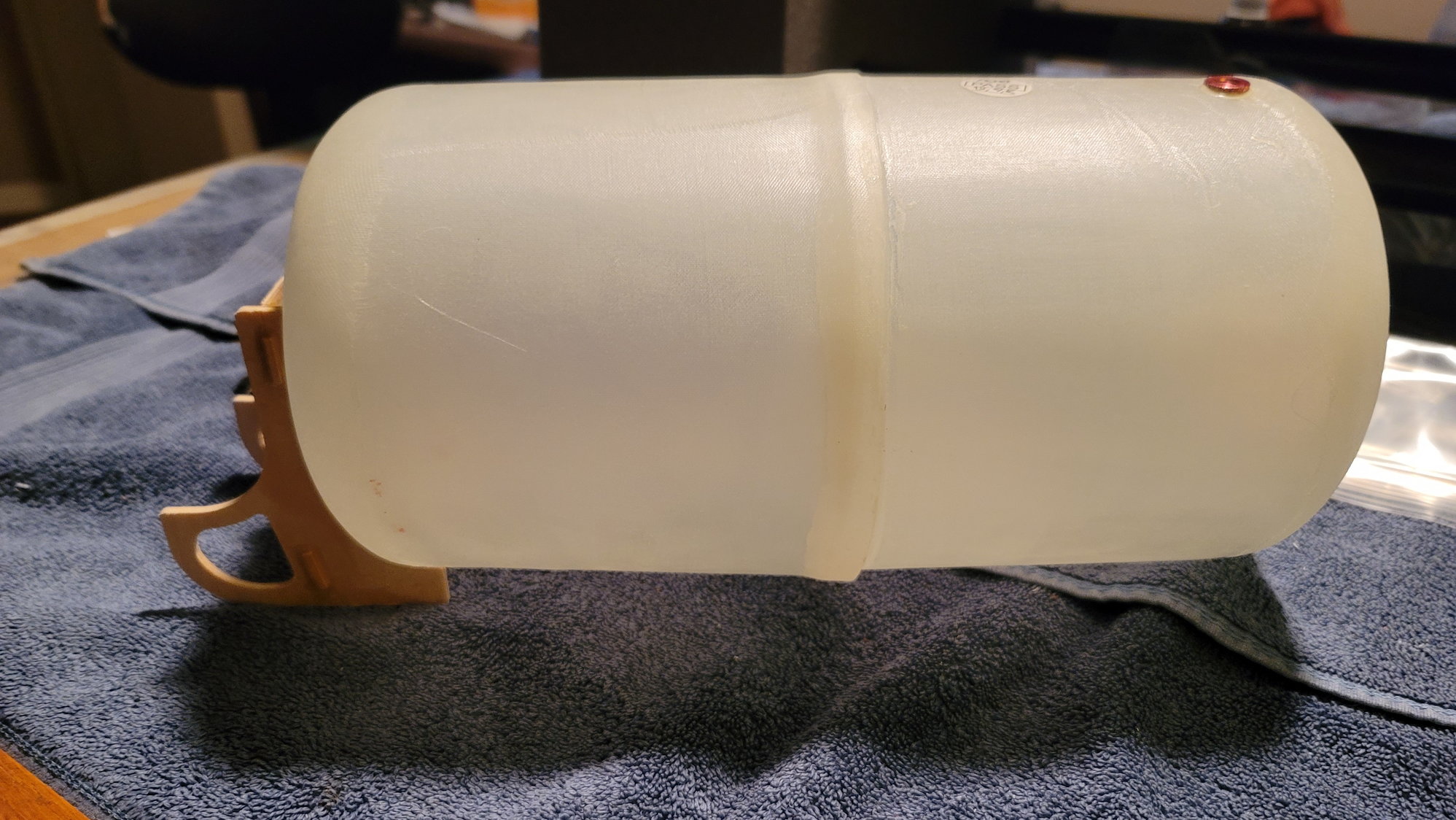
I placed the tank in through the front of the tank former and sat it in the cradle and put it under the wing tube as it would sit. Then, I had my wife hold the tank centered in the front former making sure the vent in the tank was facing up and I used medium CA and kicked it to tack the tank in the cradle in place. Then, I removed the whole structure and used Hysol 9462 to run a bead around the tank and brace, filling in the gaps between the tank and cradle. This worked very well.
The rear brace Hysol'd to the tank. Just waiting for it to dry. This brace is not designed to be glued into the plane but come out with the tank if it needs to be removed. The brace fits snuggly under the wing tube and we will glue a small piece of ply on each side of the wing tube with the tank in place to keep it from sliding sideways (per the instructions).
I thought I'd give a couple updates while I'm letting Hysol dry on the rear tank brace.
These are the 4 pieces that you need to assemble the rear tank brace. They fit very nicely together with no sanding needed.
The pieces assembled. I glued this together with medium CA and then went back and Hysol'd key areas. The cradle facing away is the part that sits under the wing tube. The cradle facing us is for the tank
I placed the tank in through the front of the tank former and sat it in the cradle and put it under the wing tube as it would sit. Then, I had my wife hold the tank centered in the front former making sure the vent in the tank was facing up and I used medium CA and kicked it to tack the tank in the cradle in place. Then, I removed the whole structure and used Hysol 9462 to run a bead around the tank and brace, filling in the gaps between the tank and cradle. This worked very well.
The rear brace Hysol'd to the tank. Just waiting for it to dry. This brace is not designed to be glued into the plane but come out with the tank if it needs to be removed. The brace fits snuggly under the wing tube and we will glue a small piece of ply on each side of the wing tube with the tank in place to keep it from sliding sideways (per the instructions).
12-24-2021, 12:55 PM
#93
Wow! You have shares in Hysol 😉
The excess ‘cream cheese’ adds nothing to the joint strength. You can get a very fine bead out of the nozzles with mild, constant pressure.
Happy Christmas
Dave
The excess ‘cream cheese’ adds nothing to the joint strength. You can get a very fine bead out of the nozzles with mild, constant pressure.
Happy Christmas
Dave
The following users liked this post:
CobraJet (04-24-2022)
12-24-2021, 12:59 PM
#94
Thread Starter
My Feedback: (1)
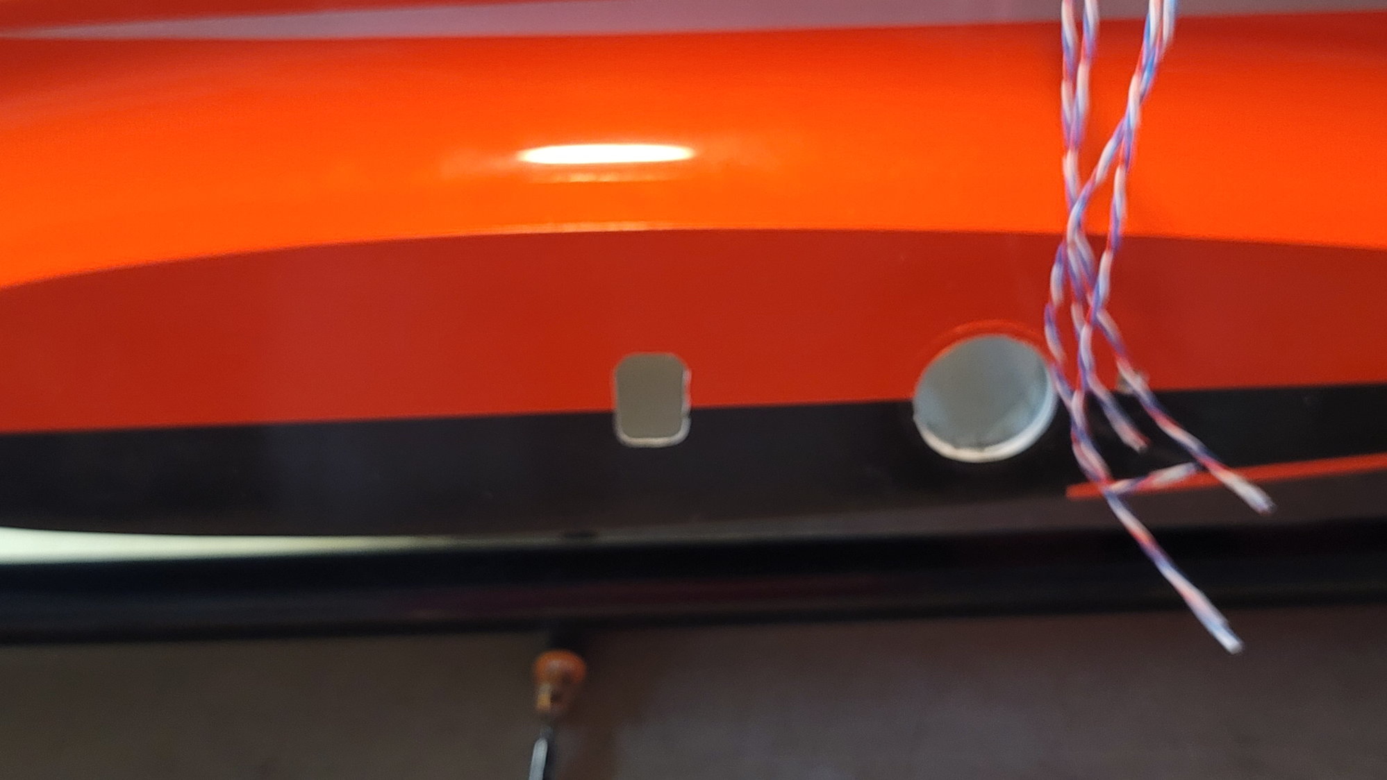
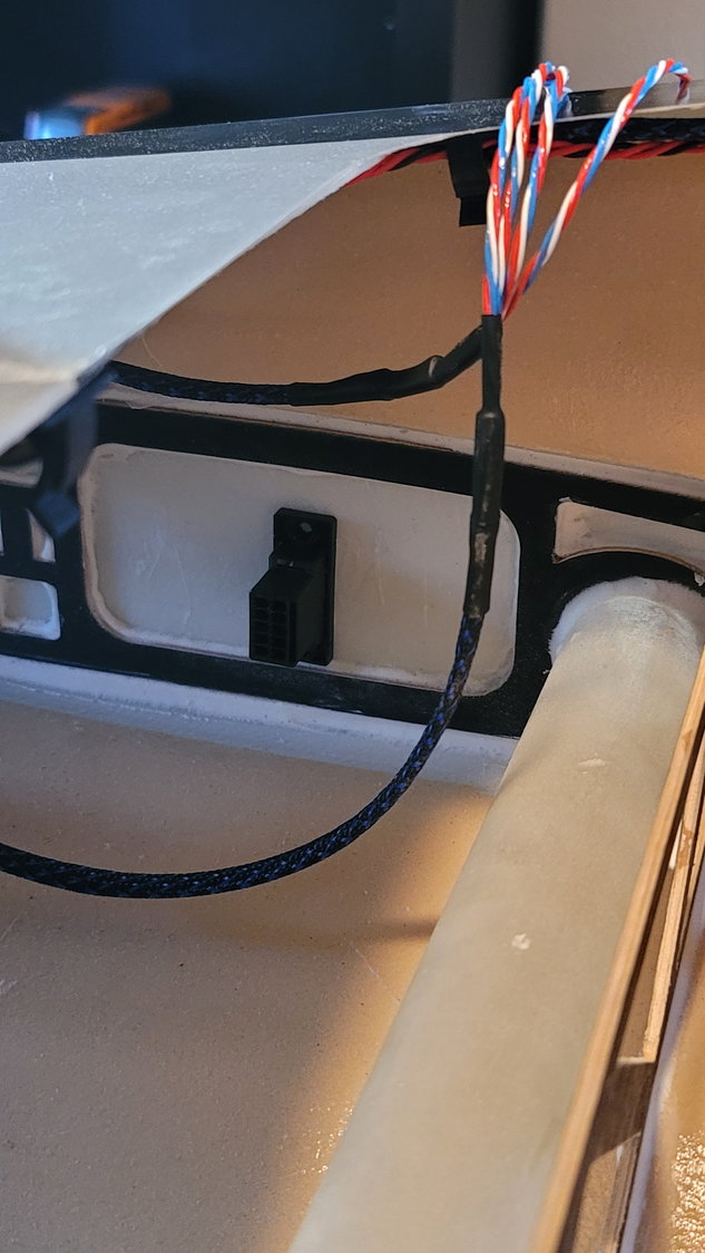
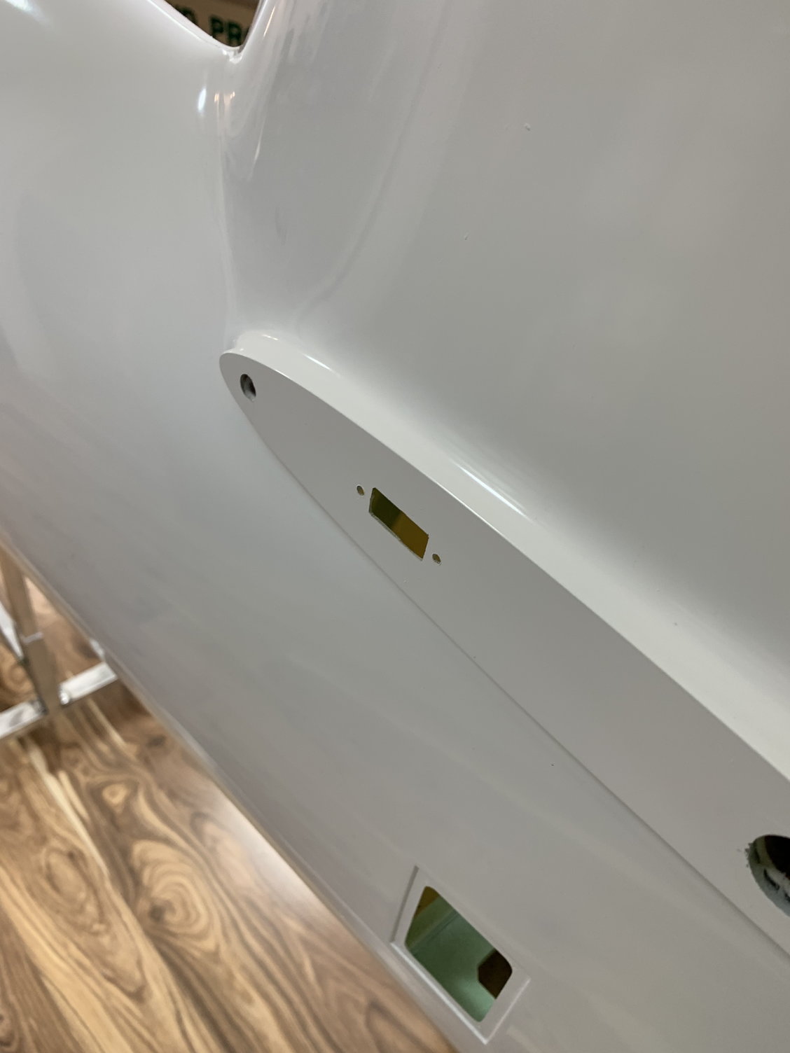
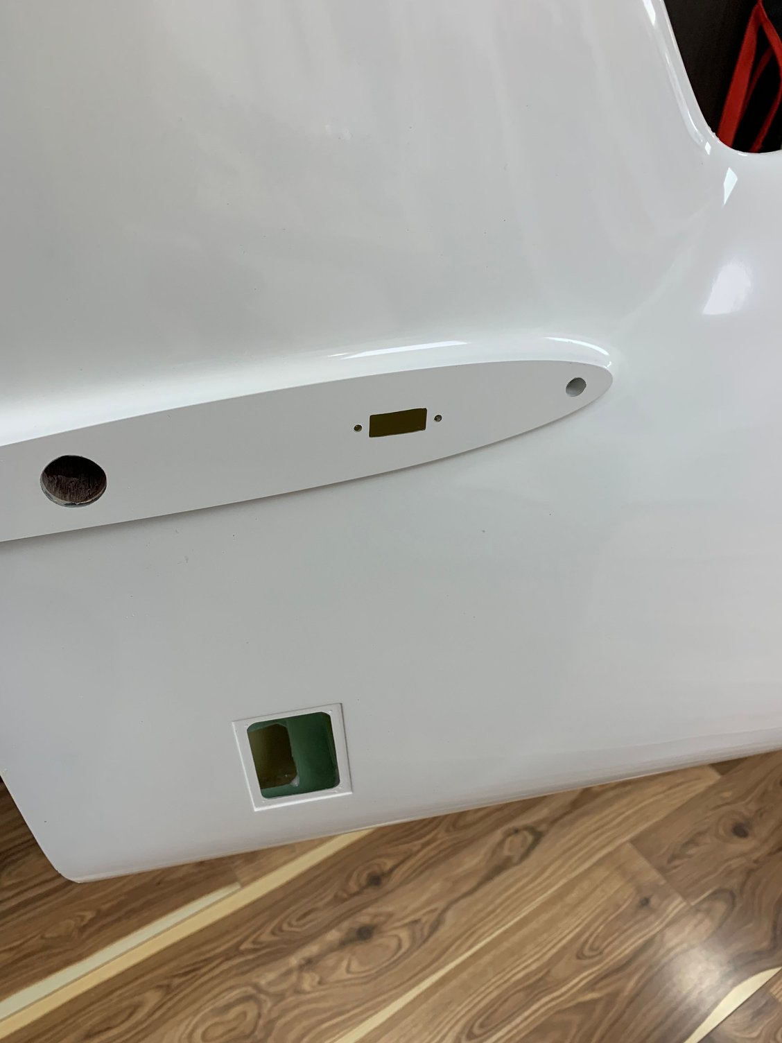
My rectangular "grommets" came in from "The Lighter Side of R/C" yesterday. In my opinion, these are a lot better than the round rubber grommets that you typically see used. They're big enough to slip any connector through, look fantastic, and are smooth enough to not have to worry about abrasion.
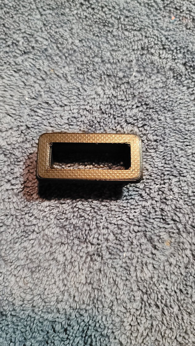
Available from "The Lighter Side of RC". Link listed in an earlier post.
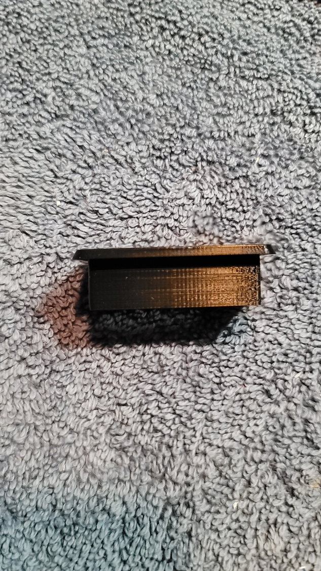
I used four of these. I cut the holes in the deck with the 1/8" ply backer, again, shown in an earlier post. These slipped right in and I glued them in place with "Amazing Goop".
I've now assembled all of my wire harnesses and am ready to put the male ends on to go to the PowerBox Competition SR2 and the Amp connectors on that go to the wings and to the rear empennage.
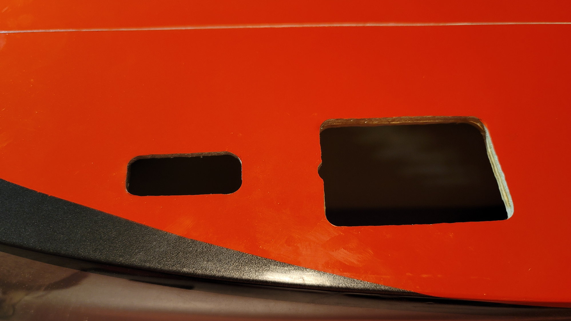
To start, I measured the distance from the spar tube in the wing to the hole also in the wing where I ran my cables out to. Then I measured the distance from the rear pin in the wing to the same hole giving me the width of that hole. Then measured the height using the black and orange painted line on the wing as reference. I then taped that off to form the box where the hole in the wing was on the root rib fillet on the fuse.
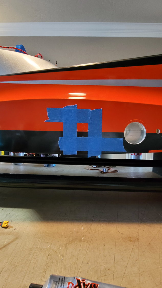
This was first drilled with a 1/16" drill bit to make sure it was coming out in an appropriate place on the fuse root rib. I then step-drilled it until I could fit my Dremel tool in and then ground it out.
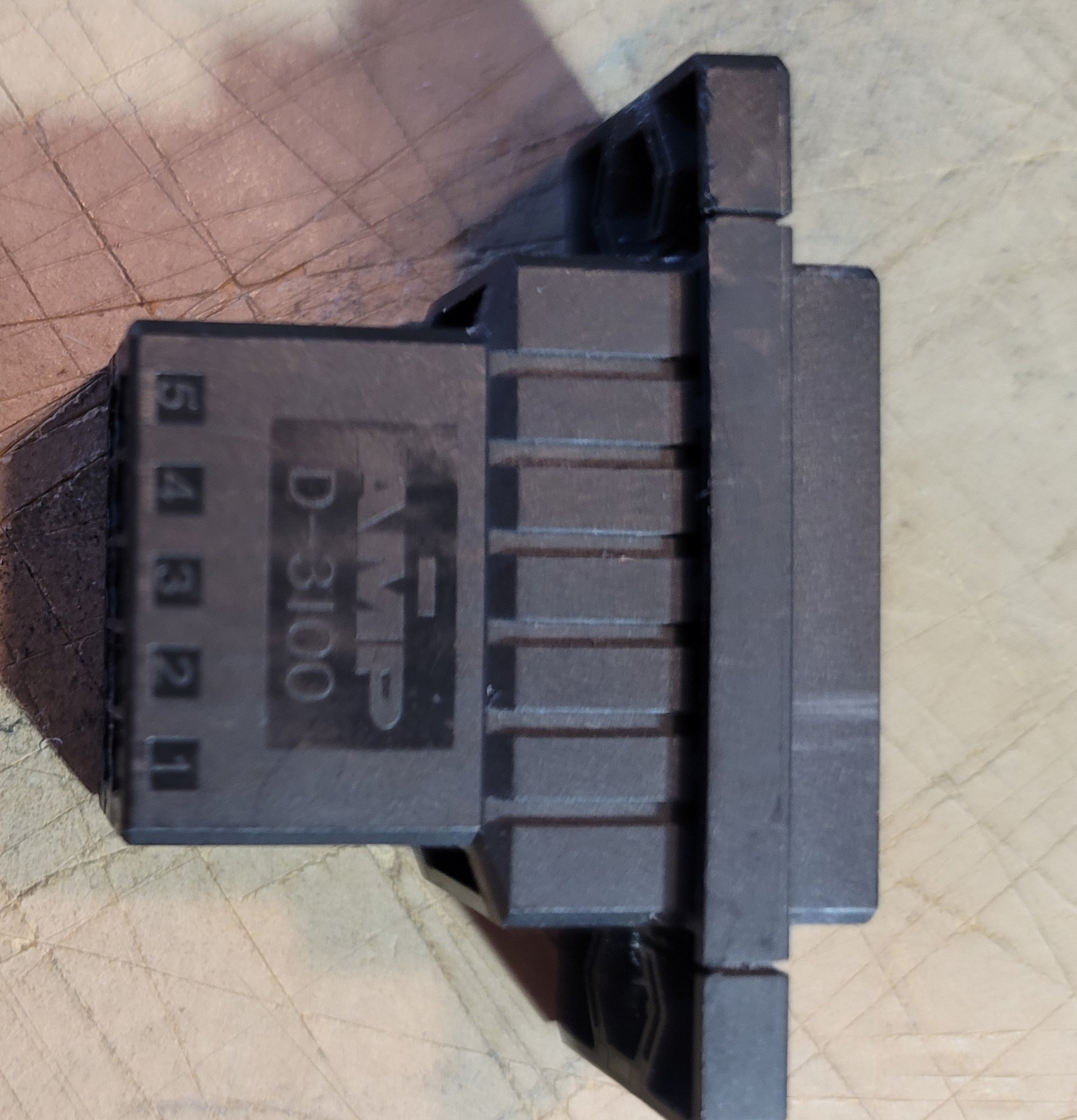
This is the Amp connector that I will use for all connections to the wings and the rear fuse half. Notice they are numbered. I will use these to determine which wire is on what pin. This will make it easy to assemble these.
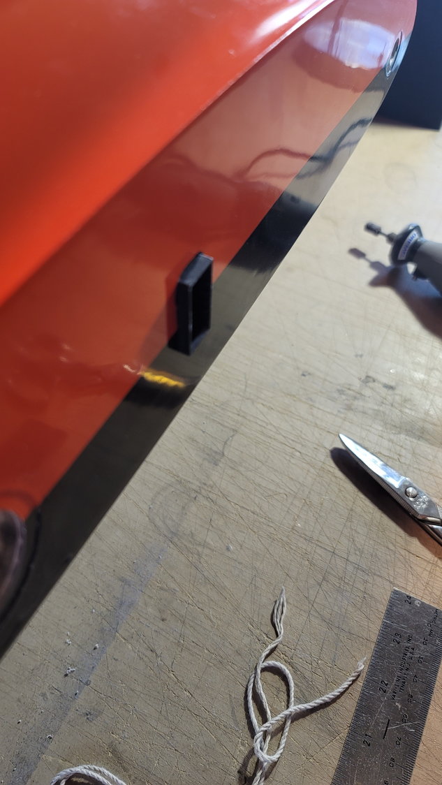
At first, I was going to mount these with the flange on the outside of the fuse and Dremel out the root rib in the wing to fit it. I realized that it was much cleaner to mount the flange on the inside so, that's what I'm doing. I will glue these in with Amazing Goop as well so if, by chance, I need to take them out, I can more easily cut them out without damage to the plane. I'll crimp the pins first before final install.
Inside the wing with the flange inside instead of out. Much cleaner.
Available from "The Lighter Side of RC". Link listed in an earlier post.
I used four of these. I cut the holes in the deck with the 1/8" ply backer, again, shown in an earlier post. These slipped right in and I glued them in place with "Amazing Goop".
I've now assembled all of my wire harnesses and am ready to put the male ends on to go to the PowerBox Competition SR2 and the Amp connectors on that go to the wings and to the rear empennage.
To start, I measured the distance from the spar tube in the wing to the hole also in the wing where I ran my cables out to. Then I measured the distance from the rear pin in the wing to the same hole giving me the width of that hole. Then measured the height using the black and orange painted line on the wing as reference. I then taped that off to form the box where the hole in the wing was on the root rib fillet on the fuse.
This was first drilled with a 1/16" drill bit to make sure it was coming out in an appropriate place on the fuse root rib. I then step-drilled it until I could fit my Dremel tool in and then ground it out.
This is the Amp connector that I will use for all connections to the wings and the rear fuse half. Notice they are numbered. I will use these to determine which wire is on what pin. This will make it easy to assemble these.
At first, I was going to mount these with the flange on the outside of the fuse and Dremel out the root rib in the wing to fit it. I realized that it was much cleaner to mount the flange on the inside so, that's what I'm doing. I will glue these in with Amazing Goop as well so if, by chance, I need to take them out, I can more easily cut them out without damage to the plane. I'll crimp the pins first before final install.
Inside the wing with the flange inside instead of out. Much cleaner.
The following users liked this post:
Canadian Man (12-26-2021)
12-24-2021, 01:07 PM
#95
Thread Starter
My Feedback: (1)
")
Also, I went back and looked at the picture....it's not NEARLY as much as it looks but still, to your point, could be thinner, I guess.
Merry Christmas Dave.
Last edited by smcharg; 12-24-2021 at 01:10 PM.
 12-24-2021, 03:01 PM
#97

My Feedback: (53)

My rectangular "grommets" came in from "The Lighter Side of R/C" yesterday. In my opinion, these are a lot better than the round rubber grommets that you typically see used. They're big enough to slip any connector through, look fantastic, and are smooth enough to not have to worry about abrasion.
Available from "The Lighter Side of RC". Link listed in an earlier post.
I used four of these. I cut the holes in the deck with the 1/8" ply backer, again, shown in an earlier post. These slipped right in and I glued them in place with "Amazing Goop".
I've now assembled all of my wire harnesses and am ready to put the male ends on to go to the PowerBox Competition SR2 and the Amp connectors on that go to the wings and to the rear empennage.
To start, I measured the distance from the spar tube in the wing to the hole also in the wing where I ran my cables out to. Then I measured the distance from the rear pin in the wing to the same hole giving me the width of that hole. Then measured the height using the black and orange painted line on the wing as reference. I then taped that off to form the box where the hole in the wing was on the root rib fillet on the fuse.
This was first drilled with a 1/16" drill bit to make sure it was coming out in an appropriate place on the fuse root rib. I then step-drilled it until I could fit my Dremel tool in and then ground it out.
This is the Amp connector that I will use for all connections to the wings and the rear fuse half. Notice they are numbered. I will use these to determine which wire is on what pin. This will make it easy to assemble these.
At first, I was going to mount these with the flange on the outside of the fuse and Dremel out the root rib in the wing to fit it. I realized that it was much cleaner to mount the flange on the inside so, that's what I'm doing. I will glue these in with Amazing Goop as well so if, by chance, I need to take them out, I can more easily cut them out without damage to the plane. I'll crimp the pins first before final install.
Inside the wing with the flange inside instead of out. Much cleaner.
This was using a hole that was already made�a little too large but it was back in 2017 ��
I do the same for the Elevator and Rudder�..if there no way to used M3 Bolts round hear or flush or normal�then I do glue them in�
Last edited by Dansy; 12-25-2021 at 05:51 AM.
The following users liked this post:
AEROSHELDON (12-24-2021)
12-24-2021, 03:02 PM
#98
Nice!
You would be amazed how little glue is needed for maximum strength, the extra thickness really does nothing except add weight.
You can hit that mount at maximum speed and snap roll it and I assure you the bracket will stay put.
Dave
You would be amazed how little glue is needed for maximum strength, the extra thickness really does nothing except add weight.
You can hit that mount at maximum speed and snap roll it and I assure you the bracket will stay put.
Dave
12-24-2021, 03:38 PM
#99
Senior Member
Nice Scott
The smoothed out Hysol just looks more professional, the weight I won't be concerned but the extra cost of the wasted hysol is hard to justify.
Good job .
The smoothed out Hysol just looks more professional, the weight I won't be concerned but the extra cost of the wasted hysol is hard to justify.
Good job .