


CARF Rebel MAX - Build Thread
 12-26-2021, 12:46 PM
#101

Thread Starter
My Feedback: (1)

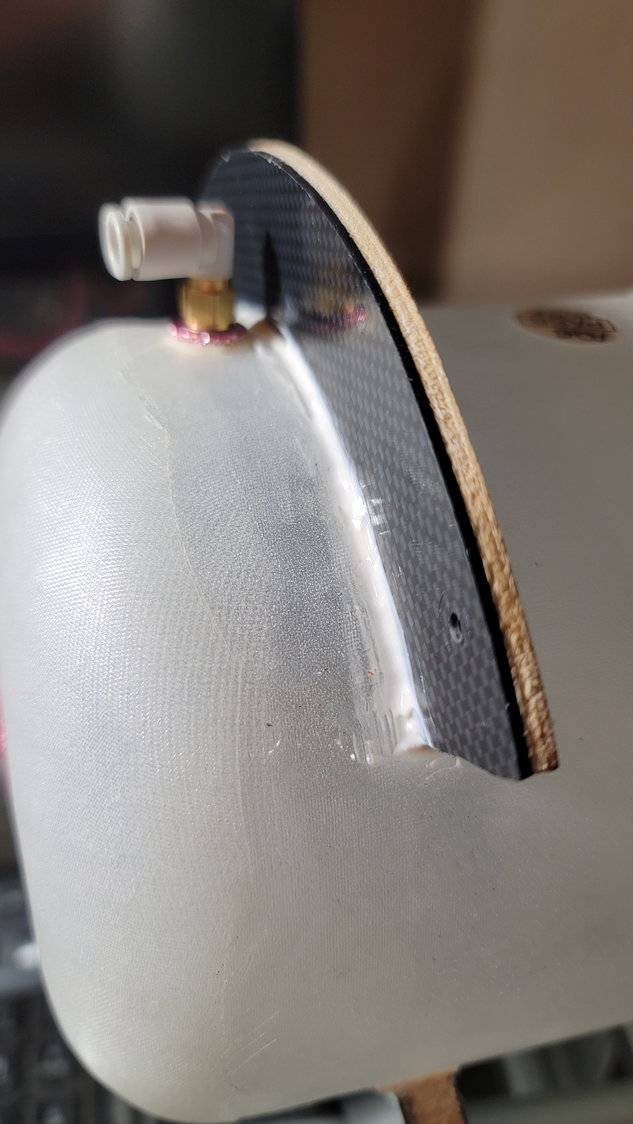
Well, Scott's a little pissy now. This is the first mistake I've found from CARF and, hopefully, the last. The top bracket for the fuel tank is too short. Even if I could redrill the holes (drilled from the factory), the bracket is still to short for the holes in the former. So, I have some questions for y'all:
As you can see on the left side, the bracket is too short to reach. Both the bracket and the former were pre-drilled at the factory.
Should I just use a 1/8" piece of plywood (I'm not sure that'd be thick enough) and trace around the existing former and make it just a bit longer so that I can reach the holes in the former? Should I rotate the bracket slightly and drill new holes in the former and use the bracket as the hole guide?
The other issue is that if I were to use the supplied bracket, even if the holes were correct, where it'd be glued to the tank is right against the vent valve on the tank unless I move the tank slightly forward. If I do this, less of the rear bracket is catching the wing tube to keep the tank in place but I think it'd be OK...just not as good as it could be.
Thoughts?
Last edited by smcharg; 12-26-2021 at 12:48 PM.
 12-26-2021, 01:23 PM
#102

My Feedback: (53)

Scott as far as I’m concerned that’s part of building….I would just trace the bracket provided…making it a little longer…and I would used ⅛ “ light ply…since it’s getting Hysol to the tank….I have seen far far worse 
12-26-2021, 03:09 PM
#103
Thread Starter
My Feedback: (1)
Dansy , you're right and I pretty much knew what I was going to do but it's always good to have confirmation. I found some stuff I used in my mini Avanti to build a tray. It's 1/8" lite ply covered by faux carbon that should look just fine from the front. I'll drill the holes to match the former and hopefully be good to go.
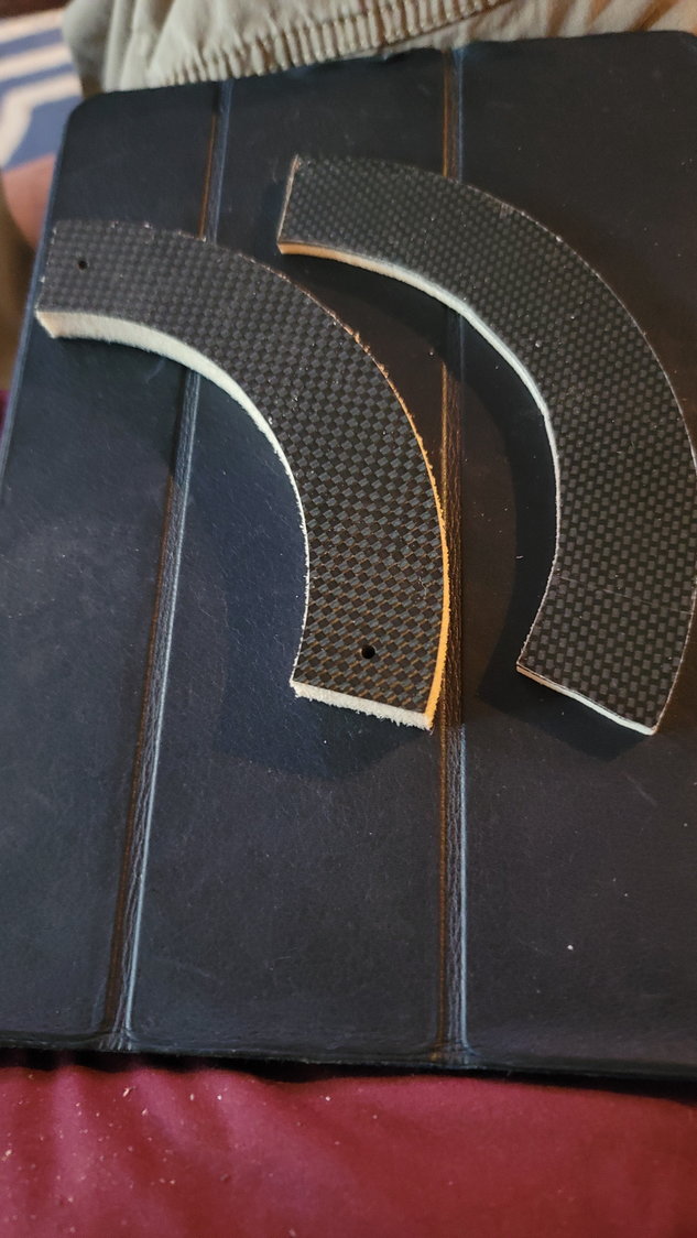
The original piece is to the left
This also should take care of the issue of the original being too thick and touching the tank's vent hole if pushed back far enough for the rear bracket to sit flush on the wing tube.
The original piece is to the left
This also should take care of the issue of the original being too thick and touching the tank's vent hole if pushed back far enough for the rear bracket to sit flush on the wing tube.
The following 2 users liked this post by smcharg:
AEROSHELDON (12-28-2021),
Dansy (12-26-2021)
12-28-2021, 05:39 AM
#104
Thread Starter
My Feedback: (1)
Tank is done. I only lack the clunk line. I'm not sure how others have done this but, what I found is that if you use the supplied upper bracket for the tank, you will have to slide the tank further forward in the front former in order to not hit the OEM tank vent. It's just too dang thick. One wouldn't think there's a problem with this and, maybe there isn't but when you do this, the rear bracket doesn't go near as far under the wing tube as it could. Since that rear bracket doesn't get glued to the tube but to the tank, this bothered me slightly. Again, that's 9 lbs. of fuel sloshing around back there. I don't want that rear bracket to come out from under the tank. So, my problem with the front top bracket being too short allowed me to build a new one half as thick which gave me the clearance to push the tank back as far as it'd go with the rear bracket under the tube and still clear the tank vent.
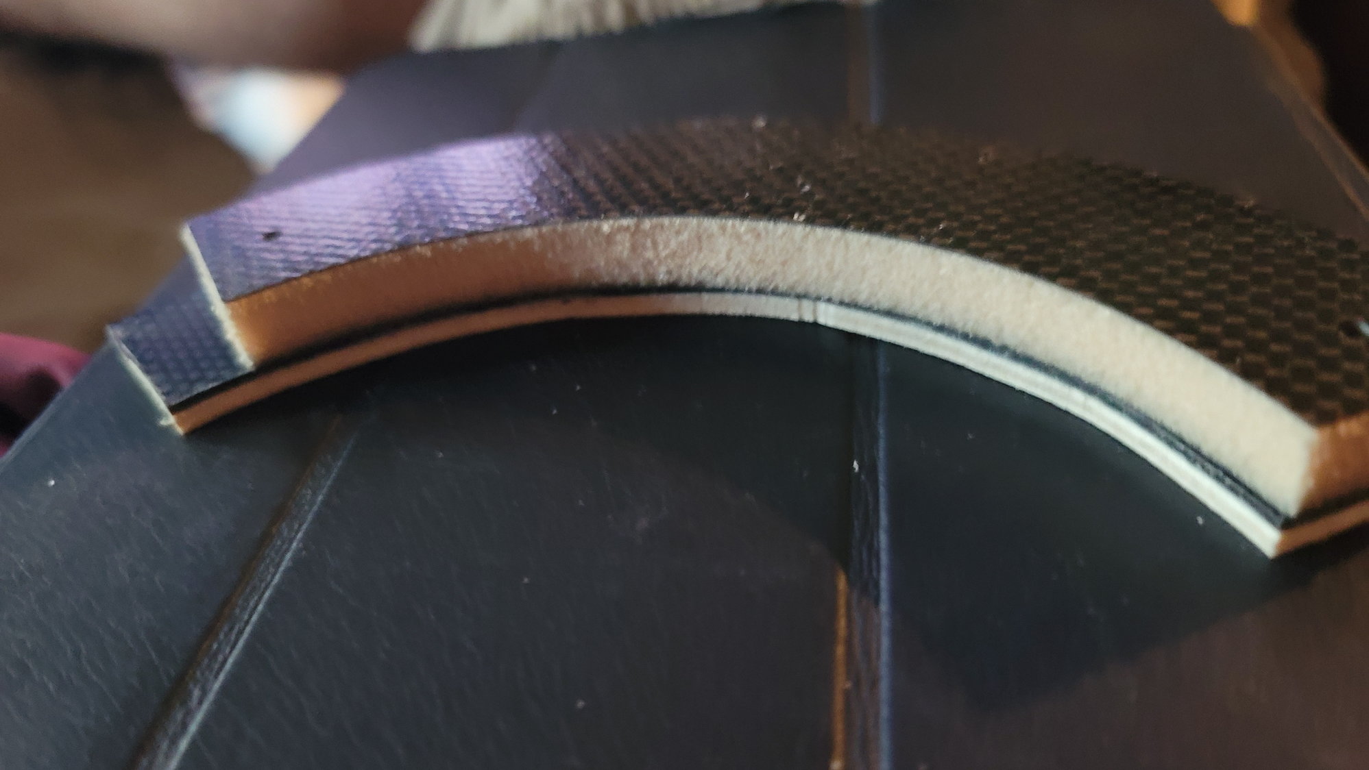
To build the new bracket, I simply took the old bracket and traced it out on a piece of 1/8" lite ply that has a piece of faux carbon laminated to the top. This piece of faux carbon is simply for aesthetics. Since it was short, I simply slid the original bracket slightly to maintain the curve for the tank to extend it. I cut it out with my scroll saw. Next, I placed the piece against the former in the plane and centered it marking the former's hole locations with a centering tool and drilled out those holes. This completed the process.
With the new piece created, I took the supplied bolts and T-Nuts and installed the T-Nuts on the aft side of the former. Once done, I mixed up some 30-minute epoxy and, sparingly, put it on the new top bracket on the side that'd attach to the tank. I installed the tank into place with the rear bracket under the tube and then placed the front top bracket on top of the tank, behind the vent and screwed in the top bracket to the former. Be careful not to get any epoxy (or whatever you use to tack the bracket to the tank) on the former as you'll not be able to remove your tank if you get any on it. Then, I took the bottom front bracket and placed it against the former and under the tank for proper fitting. I let the epoxy dry for about an hour. Once cured, I took out the easily removable bottom bracket, mixed up some 5-minute epoxy and put that on the bottom bracket and put it back into place again, being careful not to get any glue on the former between it and the bracket. Once that cured, I removed the two screws from the top former and removed the whole tank assembly with the top and bottom brackets now attached. I then simply used 9462 Hysol and permanently glued the two brackets in place.
Reever45 decided to put screws and T-Nuts on the bottom former and bracket to better secure the tank assembly. I may go back and do that as well but, I'm building this per CARF and will make that decision later.
Newly made top bracket Hysol'd in place. The bottom bracket is there too but the picture doesn't really show it.
The new bracket is 1/8" llte ply with a 1/16" faux carbon fascia. With the tank shoved all the way under the wing tube, this is the clearance to the tank vent. The OEM bracket is much thicker causing you to have to slide the tank forward slightly so that it doesn't come in contact with the tank vent. This is problematic as the rear bracket doesn't catch as much of the wing tube. Just something to keep in mind as you assemble your tank.
The following users liked this post:
AEROSHELDON (12-28-2021)
12-28-2021, 10:15 AM
#105
My Feedback: (53)
You have to remember that these CARF fuel fitting are new…..and the instruction don’t get updated….so following following the factory is not something I normally do ….I do look at them, but then decided the best way to tackle each challenges…
i would definitely want that tank to sit 100% under the tube….or change the method..
….I do look at them, but then decided the best way to tackle each challenges…i would definitely want that tank to sit 100% under the tube….or change the method..
The following users liked this post:
Canadian Man (12-29-2021)
12-28-2021, 11:07 AM
#106
Thread Starter
My Feedback: (1)
You have to remember that these CARF fuel fitting are new…..and the instruction don’t get updated….so following following the factory is not something I normally do ….I do look at them, but then decided the best way to tackle each challenges…
i would definitely want that tank to sit 100% under the tube….or change the method..
….I do look at them, but then decided the best way to tackle each challenges…i would definitely want that tank to sit 100% under the tube….or change the method..
Last edited by smcharg; 12-28-2021 at 11:14 AM.
12-29-2021, 06:03 AM
#107
Thread Starter
My Feedback: (1)
NOTE - This particular post is for those that are new to building. As I've stated, I'm trying to write this so that someone with little building experience has a detailed guide. It's how I would love a build thread to be written if I were new so, feel free to skip this post.
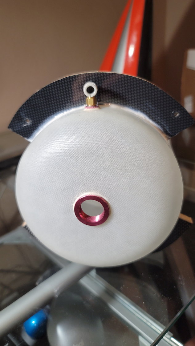
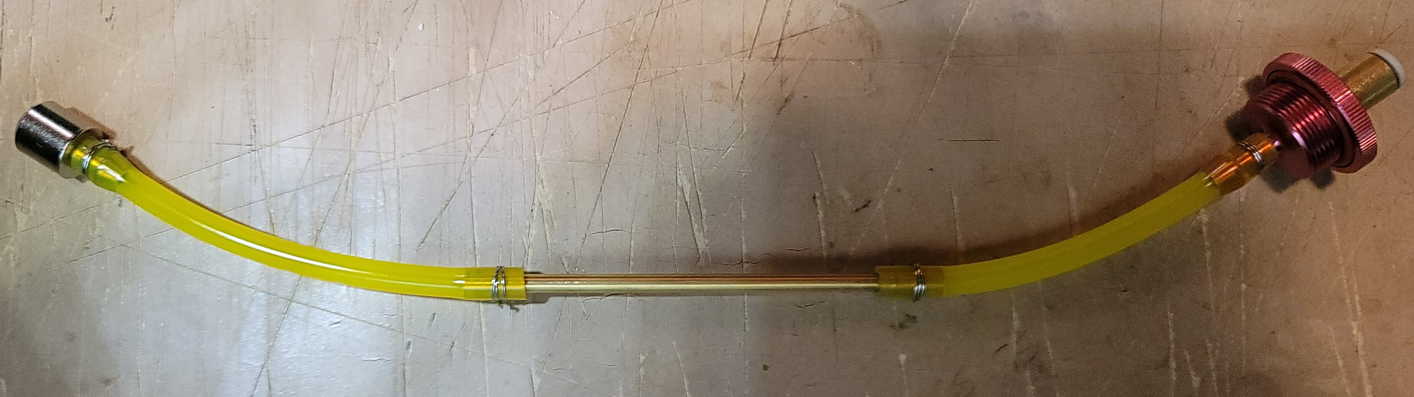
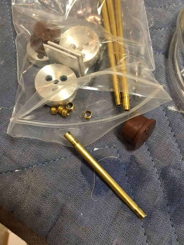
Built the "innards' to the tank last night. Very straight-forward here. The kit comes with the fuel bung (6mm), yellow tygon for the inside, brass tube, and 6mm festo tubing to go from the fuel bung to the UAT and tank vent to airplane vent in the bottom and, of course, the clunk. As we discussed earlier, the tank, being 5L / 1.3 gal., has a baffle system right in the middle of the tank to keep fuel from sloshing around. There's no need to cut the brass tube in the kit. The only thing here is to make sure that the brass tube is what's resting on the internal baffle and not the tygon. If you consider the tank has two parts, the "front" part being the fuel bung to the baffle and the "rear" part being the baffle to the back of the tank, cut a shorter piece of tygon, attach it to the fuel bung and the other end to the brass tube. Section it such that just a little bit...maybe 1/2" -1" max of the brass tube sticks through the baffle. Most of the brass tube will be in the front section and be fairly stiff. This is good as it keeps the clunk from potentially falling through the baffle (unlikely) and getting stuck in the front portion. In the rear portion, place some tygon on the brass tube and then attach the clunk. You can measure all this from the outside of the tank. Make sure your clunk just clears the bottom/rear of the tank when the clunk is centered with the tank held vertically. This is actually the shortest distance (straight line and all). If your clunk scrapes, it has potential to get stuck and not be able to freely move about the tank. Once assembled, you should be able to hear the clunk moving freely in all directions. It's very hard to see the clunk and line once inserted, even if you put a light through it but it is possible...sort of.
A few tips: First, the tygon line supplied is very tough to get on. I tried heating it slightly....didn't help. I finally went to the garage and grabbed some of my KingTech oil and just coated the nipples and brass tube. This made it much easier to get the tubing on. Second tip, while tip #1 helps and you may think there's no way that could come off, I recommend safety wiring the connections. You don't need those fancy safety wire pliers, just the safety wire, itself. Wrap the wire around the connection point (behind the barb on the nipple and clunk) twice and twist the two ends together. Keep twisting until the wire is tight around the nipple and cutoff the excess. Make sure you don't twist so much that the wire cuts into the tygon tubing. Common sense prevails here. Once the excess is cut off, use some needle-nose pliers and slightly bend in the twisted part such that it can't get caught on anything and won't stab your fuel line. Third tip, check your tank for leaks. You don't need any type of silicon or tape on the vent or fuel bung. Simply screw them in tightly. Cut off two small sections of 6mm festo tubing from the supply from the fuel tank and attach a small piece to each festo fitting. Make sure the fuel line is firmly seated in the festo fitting or you will have a leak. Pressurize the tank by blocking off the vent and blowing into the fuel bung. Listen for leaks. You can also pinch the line with a pair of pliers or hemostats as these are just scraps and let it sit for a while. Come back later and release the pinch and the compressed air should release. If not, you got yourself a leak.
Last edited by smcharg; 12-29-2021 at 12:59 PM.
The following 2 users liked this post by smcharg:
Canadian Man (12-29-2021),
Skunkwrks (12-29-2021)
12-29-2021, 12:19 PM
#108
Senior Member
Scott looks great, I did my tank exactly like this and found the Tygon didn't allow the pickup to easily move into the corners also over time it becomes less flexible.
So I removed the assembly and cut some Viton tubing and replaced the Tygon tube and found the clunk moved easily into each corner of the tank now.
The only thing I didn't do was the added some silver solder onto the brass to create a nipple for the tube to hang onto. Working with Viton tubing it needs some heat to get it to expand over the nipple on the plug end.
12-29-2021, 01:16 PM
#109
Thread Starter
My Feedback: (1)
To be honest, I haven't owned anything fuel-related except my T1 in quite some time. I have a 35% Extra but it's been at the Monokote specialist for some time. Everything has been electric for the past 12 years and I've forgotten more than I remember. One thing that I make an effort to do is to disassemble the fuel tank every year or so and replace the tygon tubing. I will continue that trend, especially with this one. I haven't tried the Viton before. I'm assuming this is the automotive stuff?
12-29-2021, 01:33 PM
#110
Senior Member
It is, you can purchase it from McMasters at a good price any length. I've used it in all my gasers and even in my fuel jugs and line for refuelling. It never gets hard like Tygon and doesn't expand in fuel like Tygon does in fuel.
I believe all the Turbine Mft don't recommend using on the supply line to and from the fuel pump as it will collapse under pressure only the clear ploy tubing that comes with the engine is too be used.
For things like the overflow vent refueling lines I've used Tygon just because I had so much to use up, I have to order a couple more feet of Viton for the Max .
12-30-2021, 05:54 PM
#111
Senior Member
Found some photos of how I assembled the Viper tank, installed it with clear ploy tubing and just Tygon for filling.
Here is the brass sleeves soldier onto the tubing prior to assembling the tank.
The other photo show the hardware for the tank, you can see the brass pieces used to create a flare on the tubing.
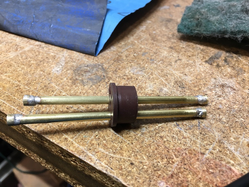
Here is the brass sleeves soldier onto the tubing prior to assembling the tank.
The other photo show the hardware for the tank, you can see the brass pieces used to create a flare on the tubing.
The following users liked this post:
smcharg (12-30-2021)
12-31-2021, 05:13 PM
#112
Thread Starter
My Feedback: (1)
Happy New Year!
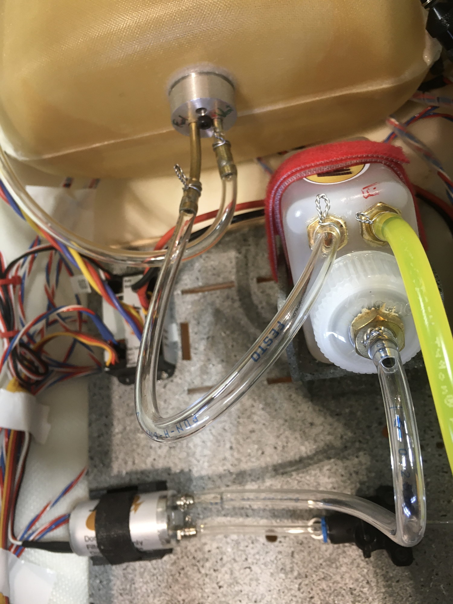
The fuel tank is now installed. Tank has been pressure tested as described earlier. 6mm urethane lines run to the vent and clunk line. I'm going to use the Digitech Mag Lock for the vent which is on its way from Australia as everyone seems to be out of stock. I used round rubber grommets to run the tank to UAT line up to the top deck.
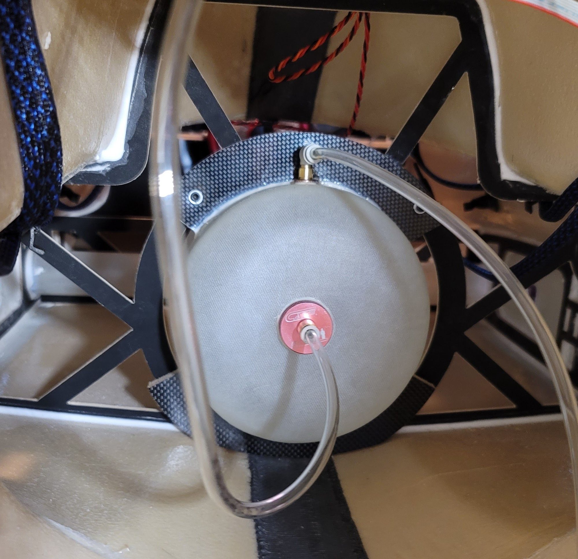
The fuel tank is now installed. Tank has been pressure tested as described earlier. 6mm urethane lines run to the vent and clunk line. I'm going to use the Digitech Mag Lock for the vent which is on its way from Australia as everyone seems to be out of stock. I used round rubber grommets to run the tank to UAT line up to the top deck.
12-31-2021, 05:24 PM
#113
Thread Starter
My Feedback: (1)
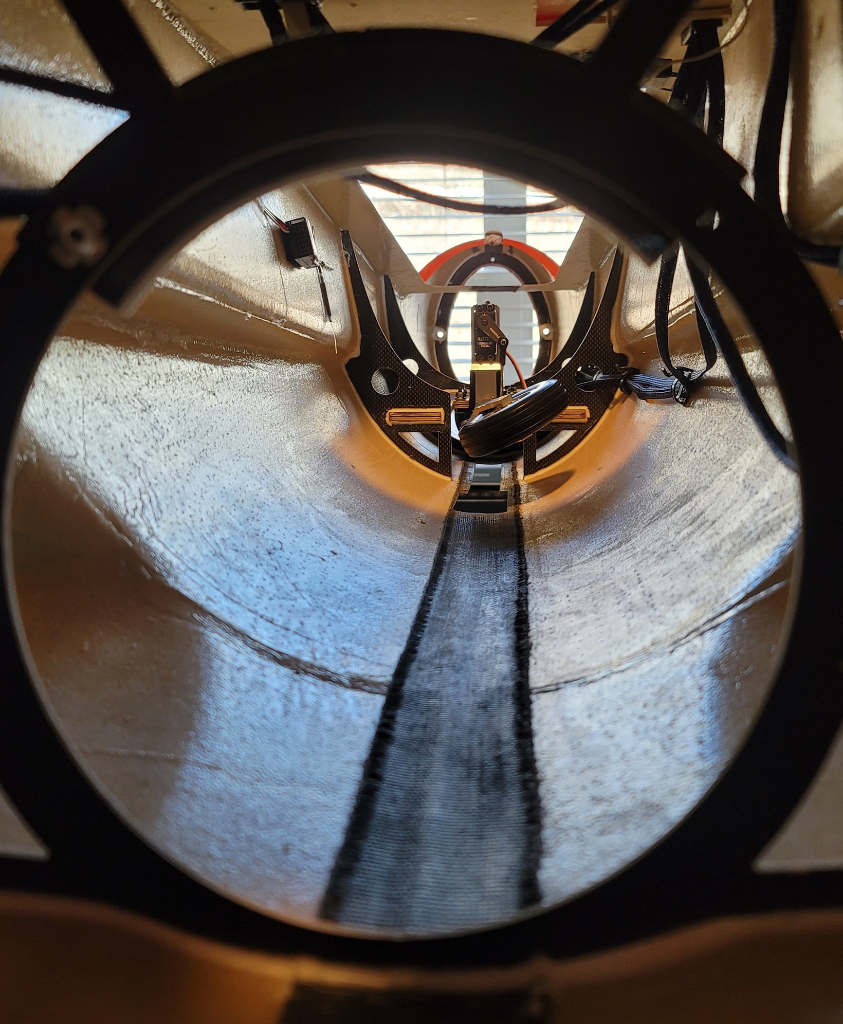
Next, I began to actually assemble the plane. This is the first time I've put the vertical fin on the fuse and, boy, this plane just gets bigger and bigger. These two pics are just to show how massive it is and the 18" nose cone is yet to go.
Vertical fin is held in with the main tube and a 4mm screw in the front of the fin that goes into a pre-installed blind nut Hysol'd into the fuse.
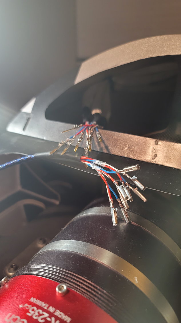
Next, I built the rear Amp connector that mounts in the rear portion of the fuse. I used the same 1/8" ply with faux carbon laminate . Per y'alls recommendation, I took 3mm socket head bolts and lock nuts which will secure the female portion in place. The male end will simply plug in there once the two sections of the fuse are bolted together.
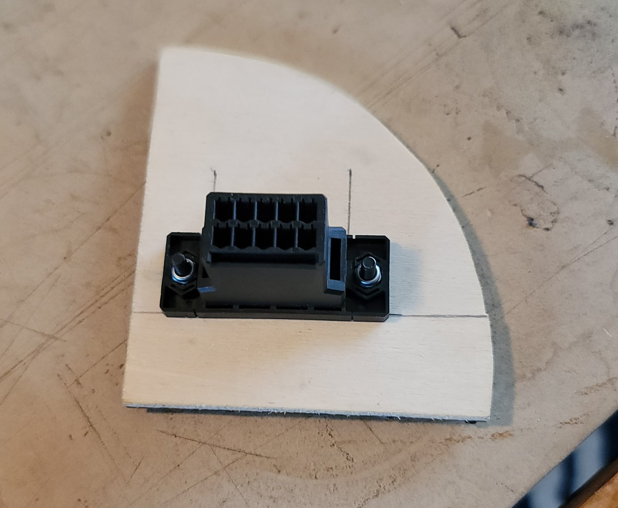
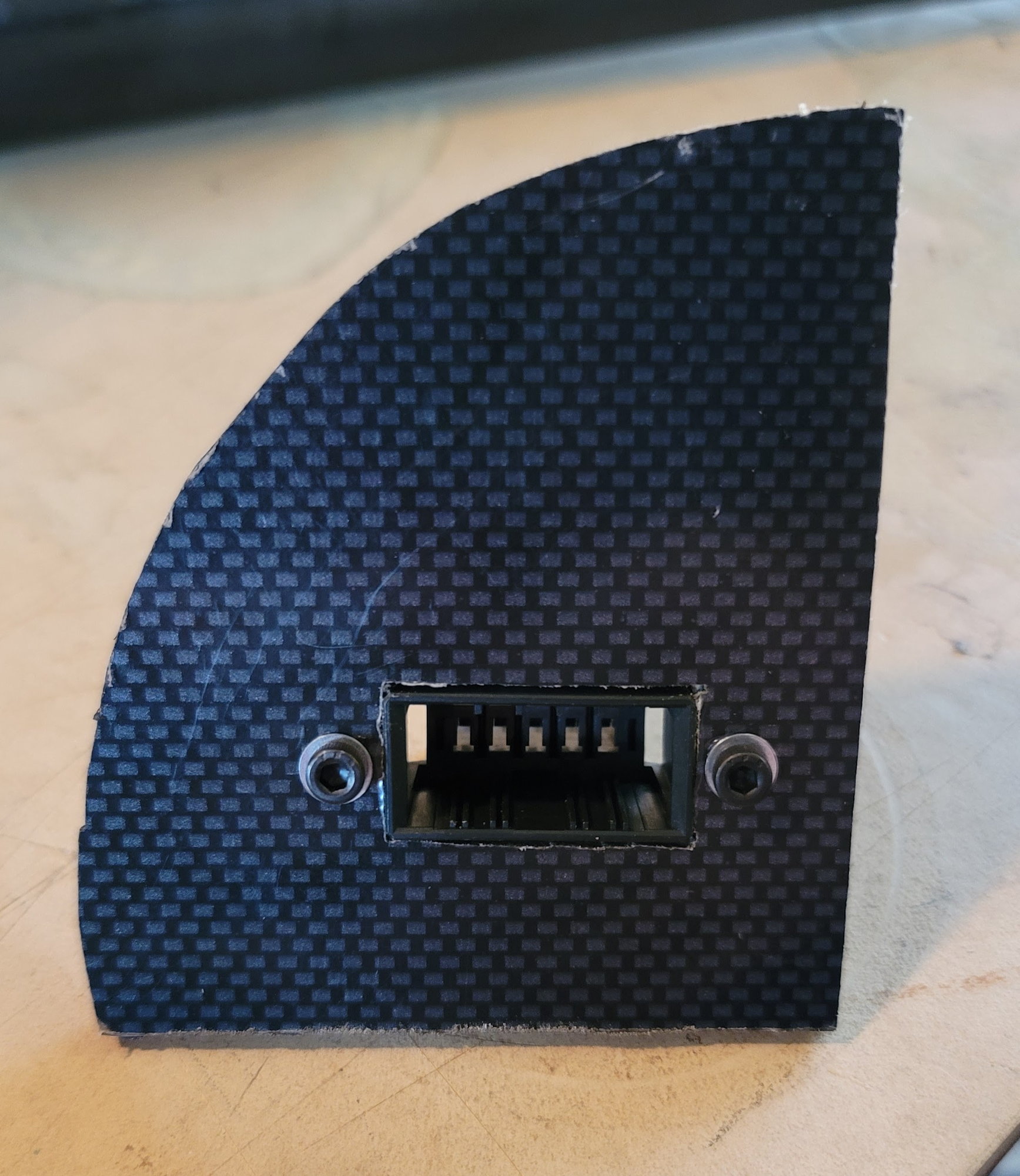
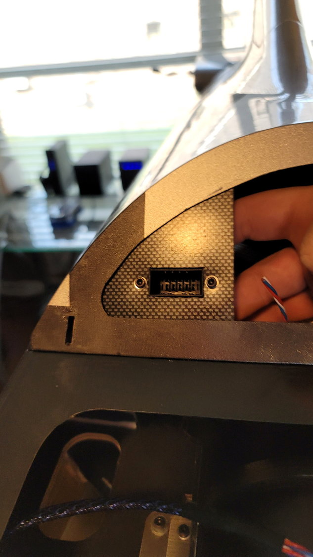
I'll Hysol this plate in something like this after we put the pins in for the rear fuse. These are 10-pin connectors. 9 pins will be used. +/- and signal for each elevator and the rudder.
Vertical fin is held in with the main tube and a 4mm screw in the front of the fin that goes into a pre-installed blind nut Hysol'd into the fuse.
Next, I built the rear Amp connector that mounts in the rear portion of the fuse. I used the same 1/8" ply with faux carbon laminate . Per y'alls recommendation, I took 3mm socket head bolts and lock nuts which will secure the female portion in place. The male end will simply plug in there once the two sections of the fuse are bolted together.
I'll Hysol this plate in something like this after we put the pins in for the rear fuse. These are 10-pin connectors. 9 pins will be used. +/- and signal for each elevator and the rudder.
The following users liked this post:
AEROSHELDON (12-31-2021)
12-31-2021, 05:34 PM
#114
Thread Starter
My Feedback: (1)
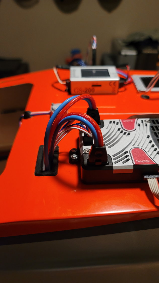
Battery wires now run to the front of the fuse. I'm using the 2500mah 2S Li-Ion packs from PowerBox and will have 2 redundant packs for the PowerBox Competition SR2 and 1 for the retracts and brakes. I won't mount the batteries until I can CG the plane (coming very soon). These packs are light (133g including mounting bracket) so I may need to use bigger packs to CG the plane. We will see. I'll also use a 3S 3800mah LiFe pack mounted in the nose for the turbine.
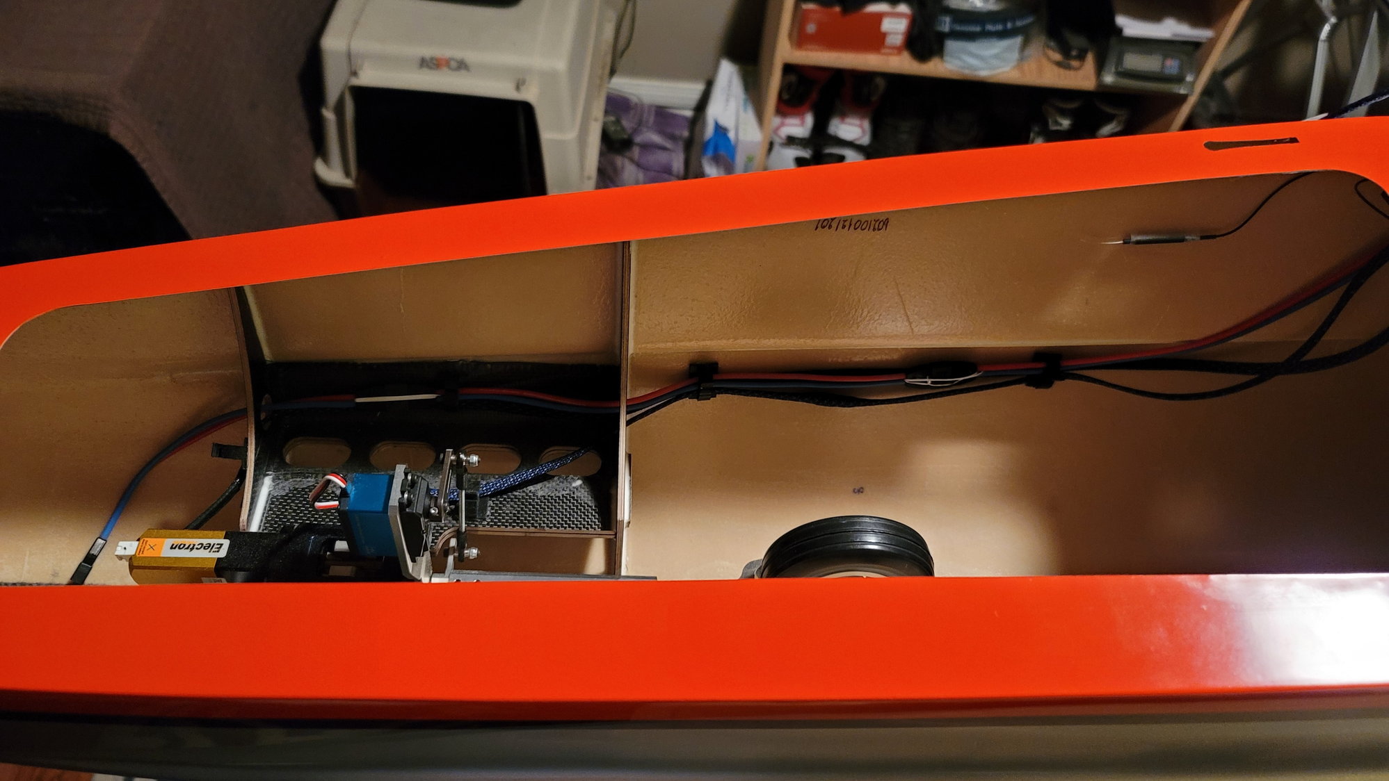
I'll tighten up the wires running up to the GS200 gear controller after I crimp on the connections
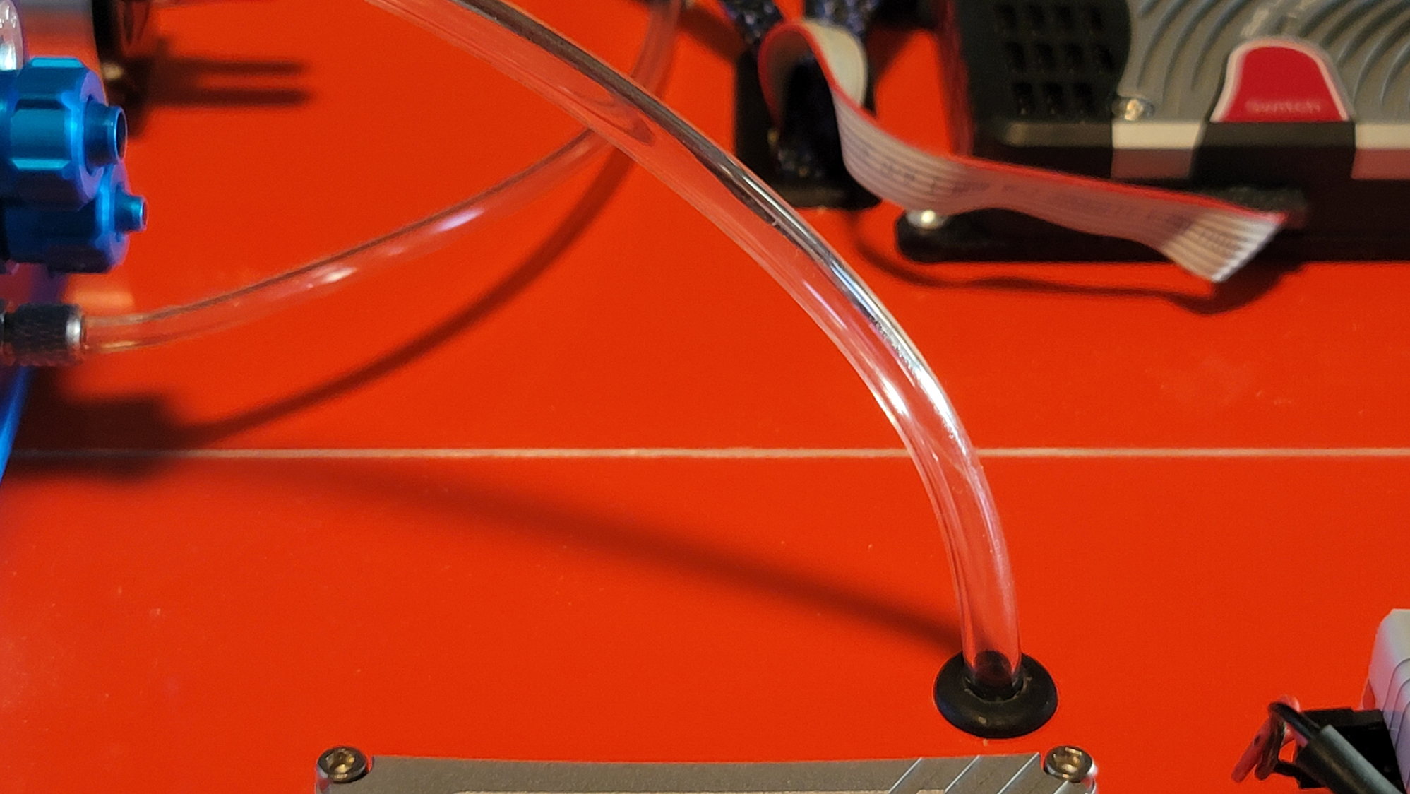
PowerBox Compettion SR2 with redundant batteries, 2 Futaba 7108 RX and iGyro SAT connected.
I used another round grommet to run the 4mm urethane fuel line from the pump on the top deck towards the turbine. I should have the turbine plumbing finished soon.
I'll tighten up the wires running up to the GS200 gear controller after I crimp on the connections
PowerBox Compettion SR2 with redundant batteries, 2 Futaba 7108 RX and iGyro SAT connected.
I used another round grommet to run the 4mm urethane fuel line from the pump on the top deck towards the turbine. I should have the turbine plumbing finished soon.
The following 2 users liked this post by smcharg:
Canadian Man (12-31-2021),
Skunkwrks (12-31-2021)
01-31-2022, 08:02 AM
#115
Thread Starter
My Feedback: (1)
I owe y'all some pictures of progress over the course of the past few weeks. I'll add more pictures beyond these soon. I wound up selling my little 6x12 trailer to a very good friend of mine and wound up buying a 7x16 and have built that out specifically for this jet (for now). That's what I've been doing. I'll give y'all some pictures once I finish the mounts using Gear Jacks from Randomheli in the trailer. To update you on the progress, the aircraft is now finished. I promise to fill in the missing steps shortly. Here's what was completed after the above post.
1. All wiring is now complete and plugged in (pictures coming)
2. Aft section of the fuse has the AMP connector glued in (pictures coming)
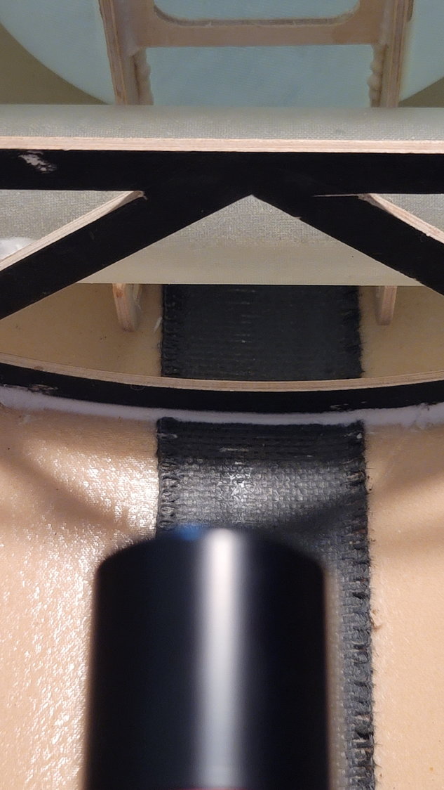
3. Braces for the rear tank so that it can't move side to side have been glued in on the bottom of the fuse at the wing spar tube (pictures coming)
4. Digitech magnetic vent plug (6mm) has been inserted into the bottom portion of the fuse near the root rib connection (pictures coming)
5. Plane has been assembled for the first time completely. Everything went together very well. I did have to grind out the opening in the wing slightly such that the wing's AMP connectors would allow the wing to sit flush against the fuse.
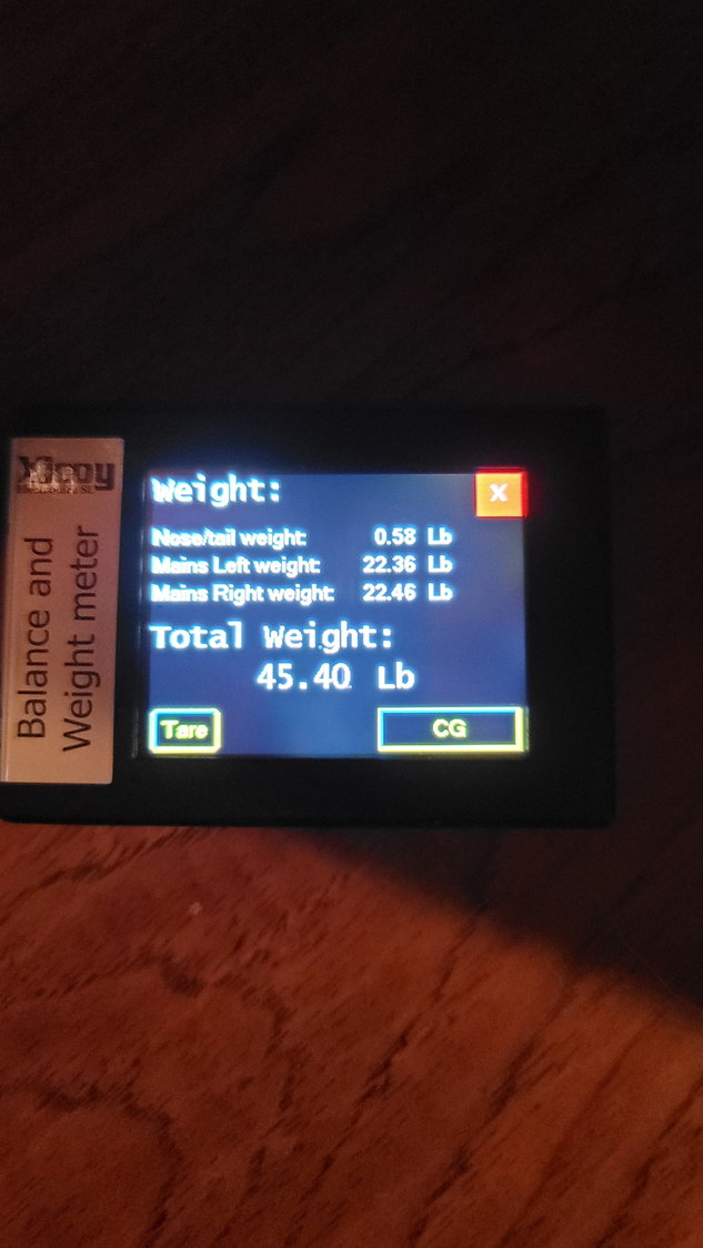
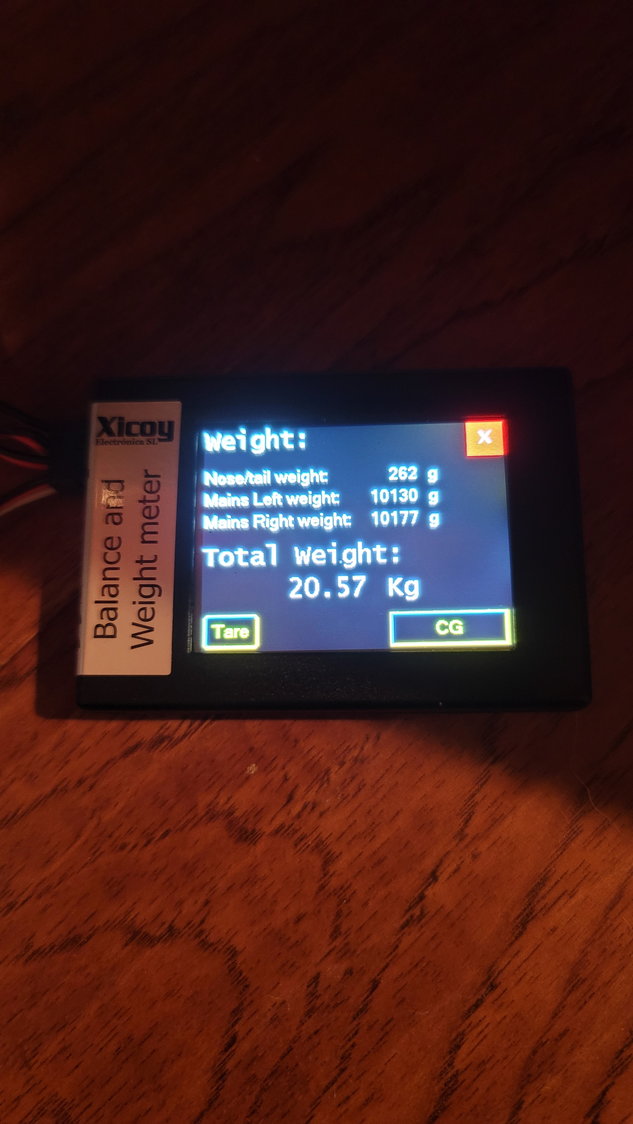
6. Plane has been weighed with UAT full (250ml) and 4 batteries included. Weight is 45.4 lbs. / 20.57 kg.
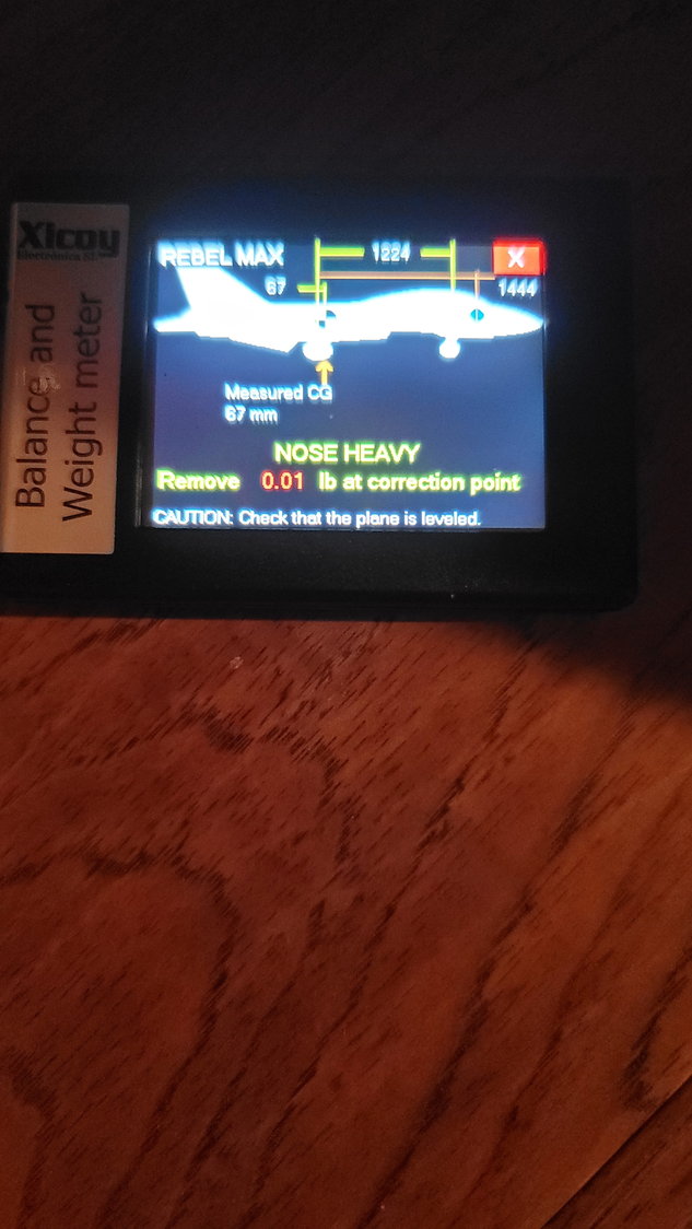
One of the things I struggled with was getting the CG set right. I was going with 2 PowerBox 2S 2500mah LiIo packs to power the redundant receivers and 1 to power the retracts and brakes. Each of these weigh 133g. I'm using the KingTech 3800mah 3S LiFe pack for the turbine. To balance, I've stuck the 3S pack in the nose cone and I'm switching to 3 2S 5000mah LiPo packs instead of the PowerBox. This adds 300 grams of weight to the nose of the aircraft (just behind where the nose cone connects to the fuse) which balances it out. The CG placement is on the ID of the back of the wing tube. For my airplane, that equates to 67mm in front of the main gear. Now, the Rebel MAX has a very large CG area. The manual says rear of wing tube +/- 20mm. Personally, I believe it is more than that but I will start here.
One thing to recall is that the main tank is 5L. That equates to 1.3 gallons and 9 pounds of weight forward of the CG if the tank is full. While it makes sense to balance it fuel tank empty, I would speculate that you won't land with an empty tank assuming you are doing due diligence on fuel burn. I haven't fueled up the jet completely but my guess is that I will be able to remove some of the weight as I start flying this giant plane and understand how she handles and understand flight time and know how much fuel is typically in the tank at the end of "x" amount of time. By the way, even CG'd this plane likes to sit on its tail with the giant canopy removed. Even with it on and fuel tank empty, it takes very little pressure on the tail to bring the nose up.
I'll list my measurements here for you for the Xicoy CG machine but I highly recommend that you get your own measurements. Use these as an approximation. I spoke with Reever45 to compare his with mine and we were about 20mm different with regards to mains to CG and we setup in pretty much the same place.
Mains to Nose = 1224mm
Mains to CG = 67mm
Mains to "correction point" (not super critical) = 1444mm
Prior to maiden, here are my throws:
40mm Ailerons and Elevator | 30% Expo
70mm Rudder | 40% Expo
Flaps Takeoff 28mm
Flaps Landing 60 degrees
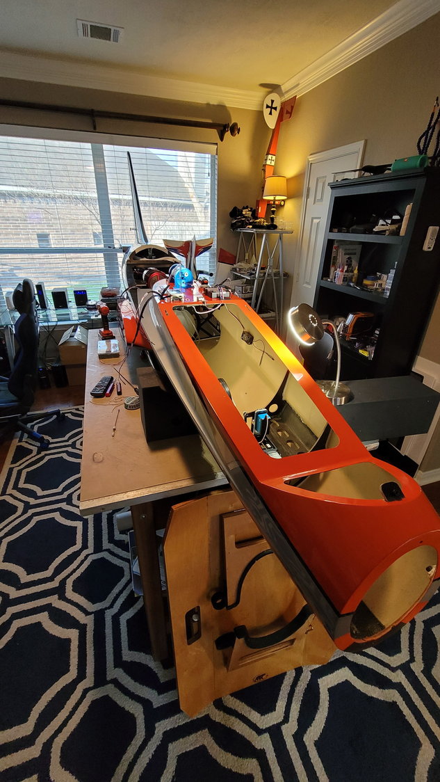
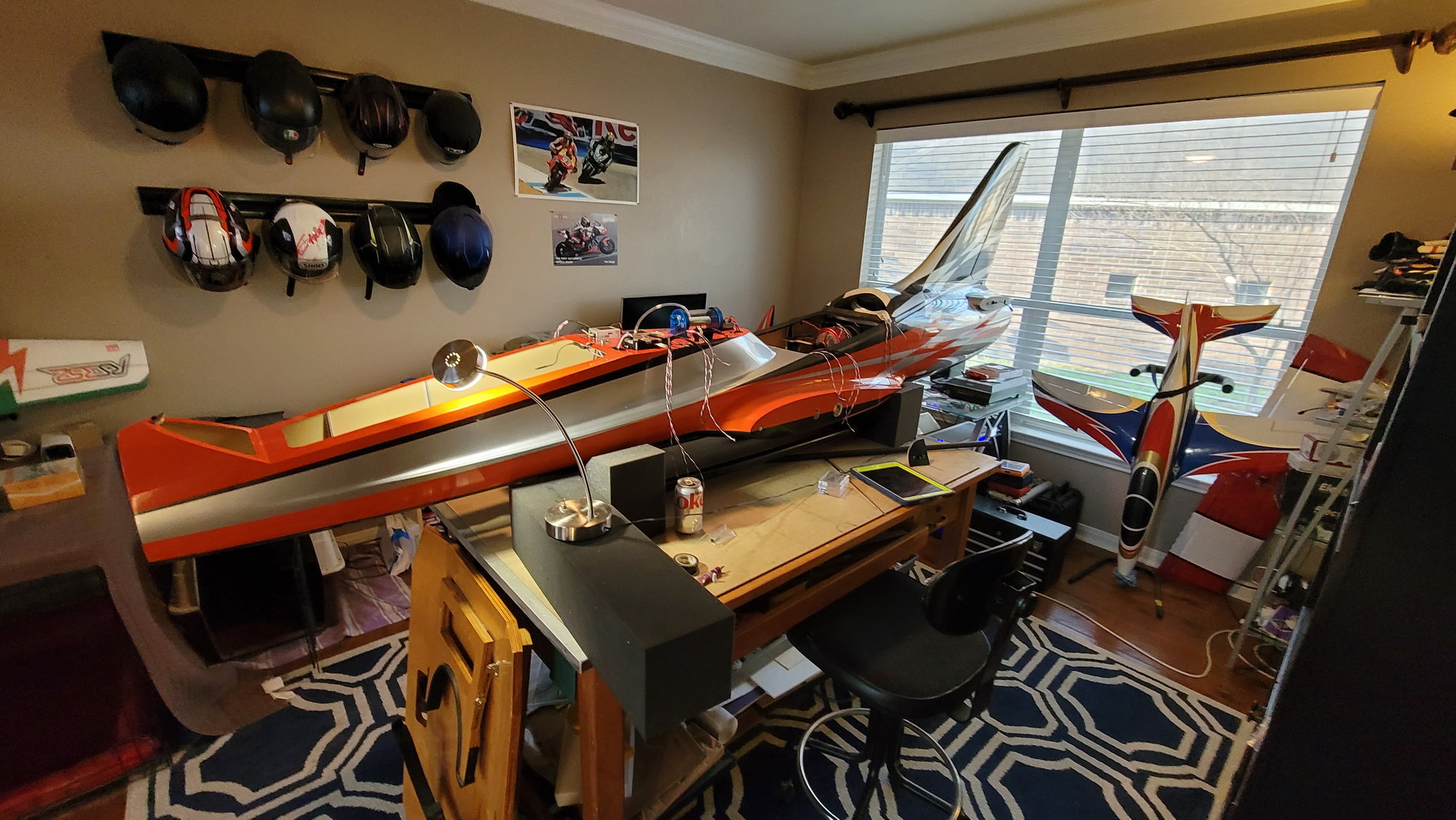
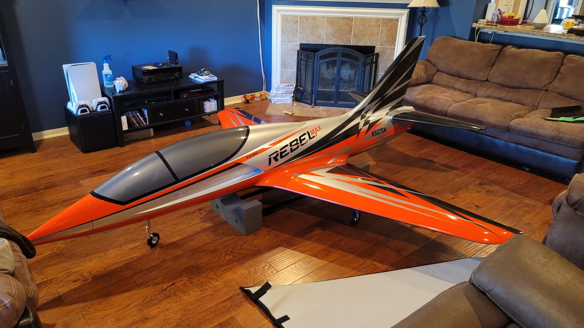
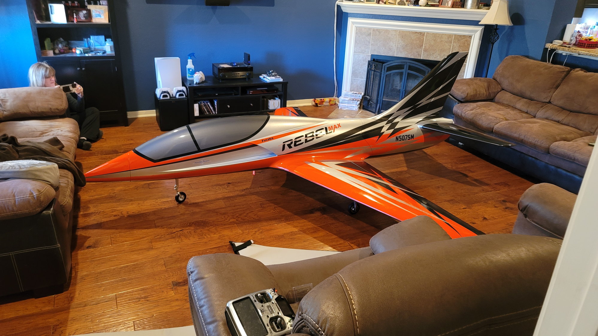
Here are some pictures I took this weekend. I have a pretty good-sized house and there was only one room I could stick this monster together. Yes, I need a workshop. I will take a few more pictures soon to fill in the gaps. Next steps are to install the battery mounts, double-check all my connections, set the main gear alignment and Loctite, and fire up the turbine. Maiden will be soon!
This is pre AMP connector
Note that the weight on the nose is pre CG. Batteries were in the plane but not in the proper position at the time of this picture.
3S 3800 LiFe shoved in the nose cone and 3x2S 5000mah LiPos against bulkhead that the nose cone connects to.
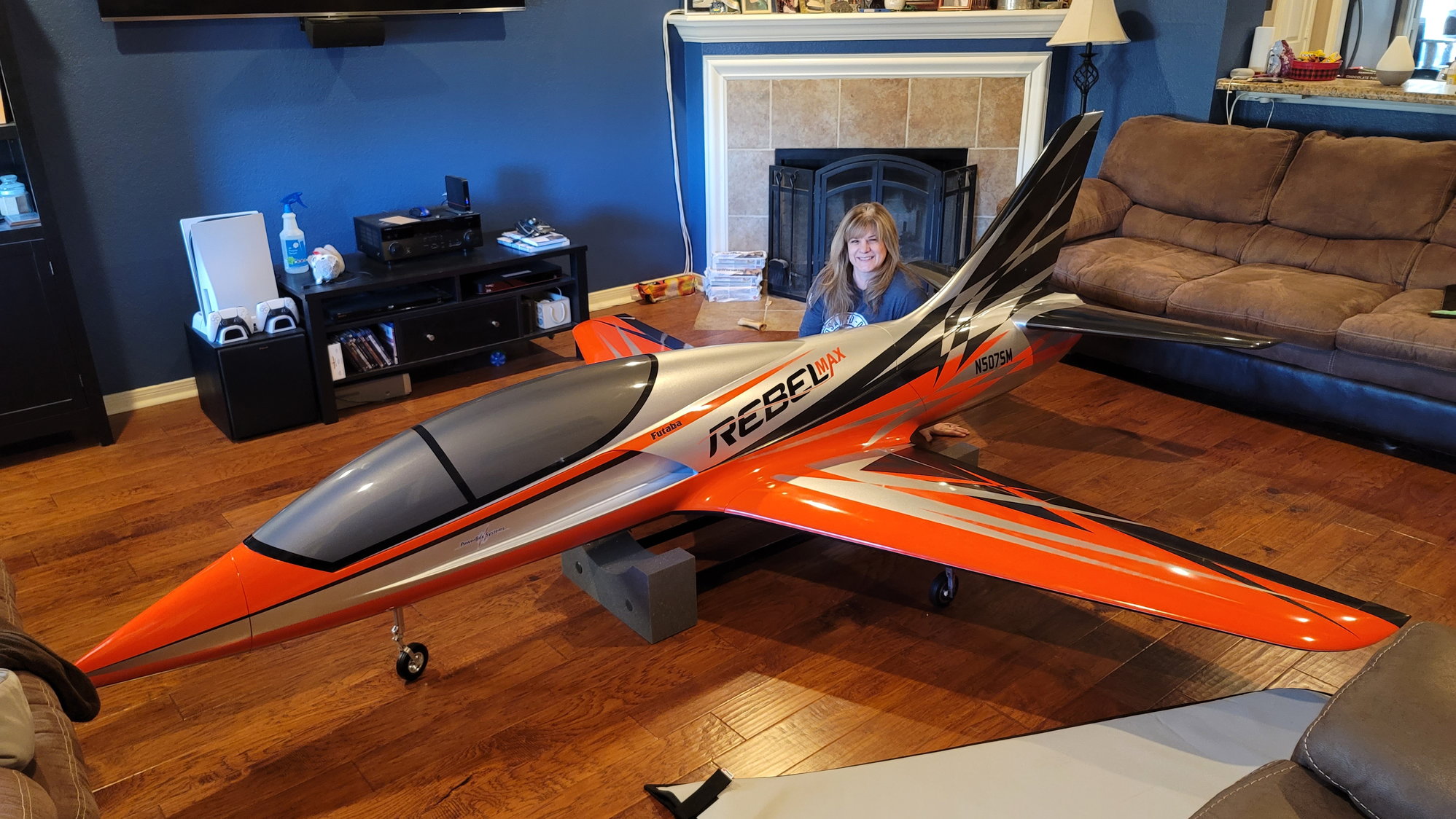
My wife almost fits in this thing!
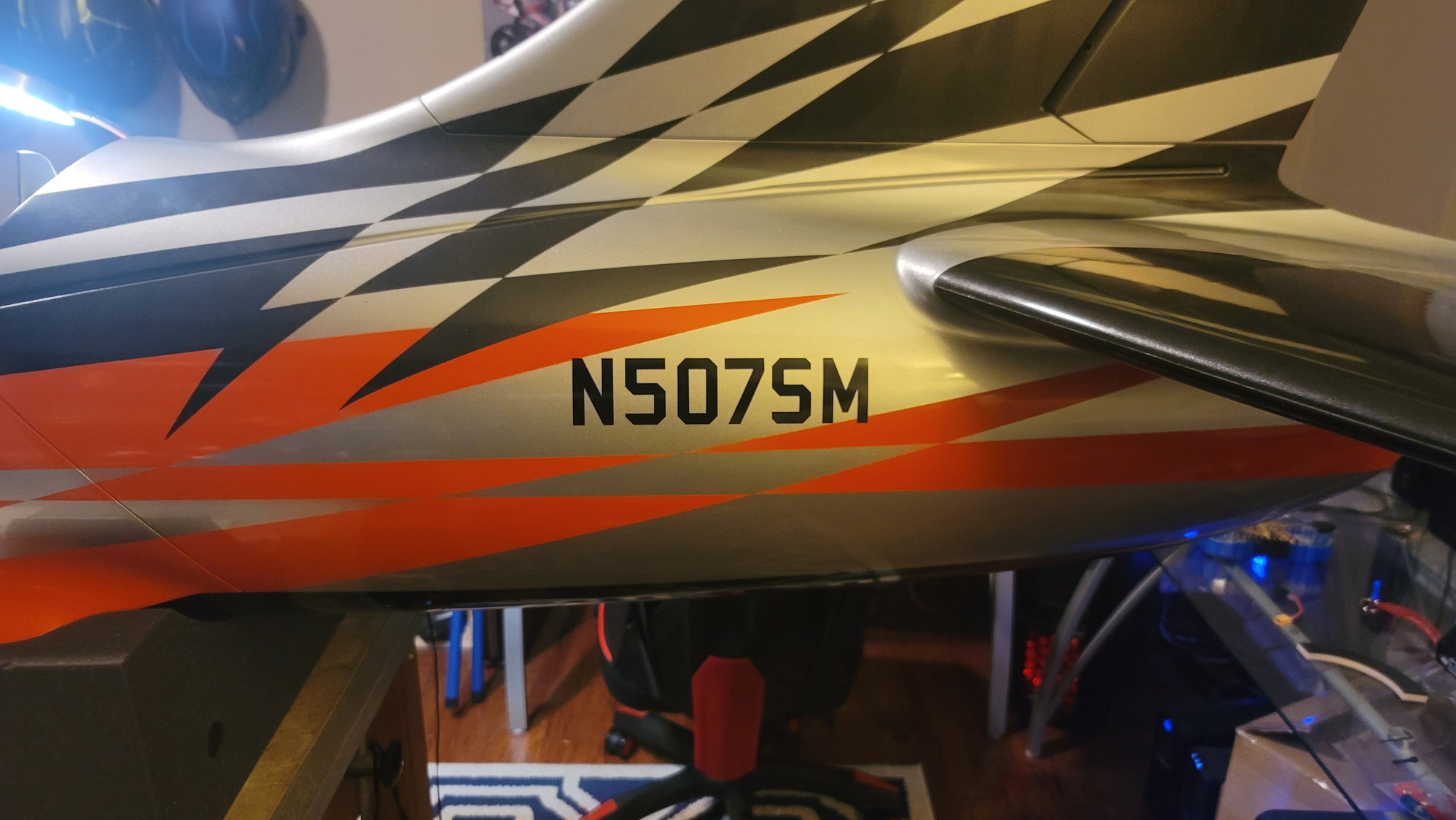
I actually bought and registered this tail number with the FAA and is my FAA number for this aircraft.
1. All wiring is now complete and plugged in (pictures coming)
2. Aft section of the fuse has the AMP connector glued in (pictures coming)
3. Braces for the rear tank so that it can't move side to side have been glued in on the bottom of the fuse at the wing spar tube (pictures coming)
4. Digitech magnetic vent plug (6mm) has been inserted into the bottom portion of the fuse near the root rib connection (pictures coming)
5. Plane has been assembled for the first time completely. Everything went together very well. I did have to grind out the opening in the wing slightly such that the wing's AMP connectors would allow the wing to sit flush against the fuse.
6. Plane has been weighed with UAT full (250ml) and 4 batteries included. Weight is 45.4 lbs. / 20.57 kg.
One of the things I struggled with was getting the CG set right. I was going with 2 PowerBox 2S 2500mah LiIo packs to power the redundant receivers and 1 to power the retracts and brakes. Each of these weigh 133g. I'm using the KingTech 3800mah 3S LiFe pack for the turbine. To balance, I've stuck the 3S pack in the nose cone and I'm switching to 3 2S 5000mah LiPo packs instead of the PowerBox. This adds 300 grams of weight to the nose of the aircraft (just behind where the nose cone connects to the fuse) which balances it out. The CG placement is on the ID of the back of the wing tube. For my airplane, that equates to 67mm in front of the main gear. Now, the Rebel MAX has a very large CG area. The manual says rear of wing tube +/- 20mm. Personally, I believe it is more than that but I will start here.
One thing to recall is that the main tank is 5L. That equates to 1.3 gallons and 9 pounds of weight forward of the CG if the tank is full. While it makes sense to balance it fuel tank empty, I would speculate that you won't land with an empty tank assuming you are doing due diligence on fuel burn. I haven't fueled up the jet completely but my guess is that I will be able to remove some of the weight as I start flying this giant plane and understand how she handles and understand flight time and know how much fuel is typically in the tank at the end of "x" amount of time. By the way, even CG'd this plane likes to sit on its tail with the giant canopy removed. Even with it on and fuel tank empty, it takes very little pressure on the tail to bring the nose up.
I'll list my measurements here for you for the Xicoy CG machine but I highly recommend that you get your own measurements. Use these as an approximation. I spoke with Reever45 to compare his with mine and we were about 20mm different with regards to mains to CG and we setup in pretty much the same place.
Mains to Nose = 1224mm
Mains to CG = 67mm
Mains to "correction point" (not super critical) = 1444mm
Prior to maiden, here are my throws:
40mm Ailerons and Elevator | 30% Expo
70mm Rudder | 40% Expo
Flaps Takeoff 28mm
Flaps Landing 60 degrees
Here are some pictures I took this weekend. I have a pretty good-sized house and there was only one room I could stick this monster together. Yes, I need a workshop. I will take a few more pictures soon to fill in the gaps. Next steps are to install the battery mounts, double-check all my connections, set the main gear alignment and Loctite, and fire up the turbine. Maiden will be soon!
This is pre AMP connector
Note that the weight on the nose is pre CG. Batteries were in the plane but not in the proper position at the time of this picture.
3S 3800 LiFe shoved in the nose cone and 3x2S 5000mah LiPos against bulkhead that the nose cone connects to.
My wife almost fits in this thing!
I actually bought and registered this tail number with the FAA and is my FAA number for this aircraft.
The following users liked this post:
AEROSHELDON (01-31-2022)
01-31-2022, 11:02 AM
#116
Senior Member
Nice setup and amazing low dry weight at 46lbs . So the CG you did was only with a fuel Map tank and nothing in the main tank.
So I guess rule of thumb is to have about 1" or 2.5cm in the tank representing an 8-9min fight time with extra fuel in the tank. You will never land with an empty tank so you should here calculate with the tanking having fuel .
The method you used would create a CG far forward of the wing tube, you should aim to Balance in the middle of the tube with 1" fuel in tank and Map full.
So slide your batteries around to reach the proper CG point, Just my two and half cents worth.
01-31-2022, 11:12 AM
#117
Thread Starter
My Feedback: (1)
So, the CG in the middle of the wing tube would be way too far forward hence setting it at the back of the tube. What you said is also what I'm saying. I'm just starting here but sure I can move some batteries around as I put flights on it. The CG is currently at the back of the tube which is where I want to start and what has been recommended. I'll build my battery trays such that I can slide them forward or backward and adjust CG based on flight results. It should work out really well.
01-31-2022, 12:09 PM
#118
Senior Member
Nice setup and amazing low dry weight at 46lbs . So the CG you did was only with a fuel Map tank and nothing in the main tank.
So I guess rule of thumb is to have about 1" or 2.5cm in the tank representing an 8-9min fight time with extra fuel in the tank. You will never land with an empty tank so you should here calculate with the tanking having fuel .
So I guess rule of thumb is to have about 1" or 2.5cm in the tank representing an 8-9min fight time with extra fuel in the tank. You will never land with an empty tank so you should here calculate with the tanking having fuel .
01-31-2022, 12:14 PM
#119
Thread Starter
My Feedback: (1)
Again, I agree with you as far as having fuel in the tank. That's what I'm planning for but I will start as recommended and fly it and see which direction I want to go. I believe the CG range on this big of an airplane is much greater than 40mm but we will start where they recommend and I will tune it to my taste and what I want to do with the plane (mainly F3S and some demo stuff for my Aerospace students at A&M). If it flies fine here, I will see how much fuel is left in the tank after "x" minutes and remove nose weight accordingly to adjust until it's where I like it. We will all see where that is.
01-31-2022, 12:35 PM
#120
Senior Member
Ah I found the manual Mike McConville sent to me for Pro and Max planes.
No manufacturer will tell you to add a reserve amount of fuel load and then balance the plane but it just common sense.
Yes back of tube to start but can vary 3/4" forward or backward.
So have your REBL on CG pucks and added some (1") fuel and see how forward the CG changes then empty and then mark the CG.
01-31-2022, 12:40 PM
#121
Senior Member
What would be the eye opener is checking the CG with full tanks and measure.
01-31-2022, 01:22 PM
#122
Thread Starter
My Feedback: (1)
Yup to all that. But, as you can see...the wife is involved in this. Imagine bringing a plane filled with JET A into the house. That's not gonna happen. All that will be obtained but will have to wait until I go to the field.
The following users liked this post:
Skunkwrks (01-31-2022)
01-31-2022, 03:45 PM
#123
I owe y'all some pictures of progress over the course of the past few weeks. I'll add more pictures beyond these soon. I wound up selling my little 6x12 trailer to a very good friend of mine and wound up buying a 7x16 and have built that out specifically for this jet (for now). That's what I've been doing. I'll give y'all some pictures once I finish the mounts using Gear Jacks from Randomheli in the trailer. To update you on the progress, the aircraft is now finished. I promise to fill in the missing steps shortly. Here's what was completed after the above post.
1. All wiring is now complete and plugged in (pictures coming)
2. Aft section of the fuse has the AMP connector glued in (pictures coming)
3. Braces for the rear tank so that it can't move side to side have been glued in on the bottom of the fuse at the wing spar tube (pictures coming)
4. Digitech magnetic vent plug (6mm) has been inserted into the bottom portion of the fuse near the root rib connection (pictures coming)
5. Plane has been assembled for the first time completely. Everything went together very well. I did have to grind out the opening in the wing slightly such that the wing's AMP connectors would allow the wing to sit flush against the fuse.
6. Plane has been weighed with UAT full (250ml) and 4 batteries included. Weight is 45.4 lbs. / 20.57 kg.
One of the things I struggled with was getting the CG set right. I was going with 2 PowerBox 2S 2500mah LiIo packs to power the redundant receivers and 1 to power the retracts and brakes. Each of these weigh 133g. I'm using the KingTech 3800mah 3S LiFe pack for the turbine. To balance, I've stuck the 3S pack in the nose cone and I'm switching to 3 2S 5000mah LiPo packs instead of the PowerBox. This adds 300 grams of weight to the nose of the aircraft (just behind where the nose cone connects to the fuse) which balances it out. The CG placement is on the ID of the back of the wing tube. For my airplane, that equates to 67mm in front of the main gear. Now, the Rebel MAX has a very large CG area. The manual says rear of wing tube +/- 20mm. Personally, I believe it is more than that but I will start here.
One thing to recall is that the main tank is 5L. That equates to 1.3 gallons and 9 pounds of weight forward of the CG if the tank is full. While it makes sense to balance it fuel tank empty, I would speculate that you won't land with an empty tank assuming you are doing due diligence on fuel burn. I haven't fueled up the jet completely but my guess is that I will be able to remove some of the weight as I start flying this giant plane and understand how she handles and understand flight time and know how much fuel is typically in the tank at the end of "x" amount of time. By the way, even CG'd this plane likes to sit on its tail with the giant canopy removed. Even with it on and fuel tank empty, it takes very little pressure on the tail to bring the nose up.
I'll list my measurements here for you for the Xicoy CG machine but I highly recommend that you get your own measurements. Use these as an approximation. I spoke with Reever45 to compare his with mine and we were about 20mm different with regards to mains to CG and we setup in pretty much the same place.
Mains to Nose = 1224mm
Mains to CG = 67mm
Mains to "correction point" (not super critical) = 1444mm
Prior to maiden, here are my throws:
40mm Ailerons and Elevator | 30% Expo
70mm Rudder | 40% Expo
Flaps Takeoff 28mm
Flaps Landing 60 degrees
Here are some pictures I took this weekend. I have a pretty good-sized house and there was only one room I could stick this monster together. Yes, I need a workshop. I will take a few more pictures soon to fill in the gaps. Next steps are to install the battery mounts, double-check all my connections, set the main gear alignment and Loctite, and fire up the turbine. Maiden will be soon!
This is pre AMP connector
Note that the weight on the nose is pre CG. Batteries were in the plane but not in the proper position at the time of this picture.
3S 3800 LiFe shoved in the nose cone and 3x2S 5000mah LiPos against bulkhead that the nose cone connects to.
My wife almost fits in this thing!
I actually bought and registered this tail number with the FAA and is my FAA number for this aircraft.
Thanks,
Tone
01-31-2022, 05:22 PM
#124
Senior Member
02-01-2022, 05:03 AM
#125
Thread Starter
My Feedback: (1)
That is the large stand from Pacific R/C Jets. I actually need to buy a second one for when I take apart this jet for the aft section of the fuse. Here's the link: https://pacificrcjets.com/collection...19083570774112
The small stand easily fits 2.2m jets. The large one holds bigger.
The small stand easily fits 2.2m jets. The large one holds bigger.