


8th Scale Aviation's, "CzechMate" Short-kit, Group build


 12-13-2015, 03:35 PM
#53

Thread Starter

It is difficult to know how much to break the process down. But, Airraptor did ask Tim to ask me to try to give a little more detail in my build notes, so that G-Man would be able to build his easier, beings I guess he doesn't have a lot of building experience from kits. I'm trying to strike a balance between easy readability, yet sufficient detail for inexperienced builders. Hopefully, I am able to show just how easy (and in my opinion, MORE FUN) it is to build one of these kits. Eric has never built a kit before, and he is having a BLAST, and has really learned a great deal!
The real beauty is that Tim designs all his kits very similarly, from one design to the next, so the construction steps and techniques listed here apply nearly directly to any of his other designs. I would think that anyone interested in building one of these kits would feel very supported, having a lot of reference material accessible right here in the Scale Racing forum. (Tim and Jake completed the three videos documenting the step-by-step building of the TA-152 wing, Jake has had some videos detailing the build of his Me209, Tim is documenting his Bearcat build, Jeff logged some of his Tsunami build, and then there is this thread, of course.) I'd love to see Gary get his kit and start building it along with us -- along with anyone else that may be interested in this model. That way, if anyone does have questions or needs help, Tim and I can answer them by demonstrating with specific, close-up pictures we can take, and more specific directions as needed, as we build ours. In fact, I have too many weekend commitments over this holiday break, so I have to take about a 3-week break from the build, until January 9-10, when we can all get together on a weekend, again. So that gives anyone interested plenty of time to get started and caught-up with us.
I'm excited you picked up a Tsunami kit, Marty. Jeff really liked his, and they were impressive on the race course. Feel free to ask questions about the build on this thread, if you'd like; or, better yet, start a new one. Tim and I will be watching, and will be happy to help in any way we can, should you need it. I don't think you'll find it at all difficult, however -- everything has been pretty straight-forward, thus far. (I just got my hands on one of the Conquest 1 kits, too!)
12-13-2015, 03:54 PM
#54
Thread Starter
I just re-loaded the pictures towards the end of the last page, if any of you were having trouble viewing them. The thumbnails did not appear at all, but I was at least able to view the attached photos on posts 48 - 50. All should be better functioning, now. Sorry, but I was posting these at about 1:30 in the morning, and I was too tired to try to fix it at that time.
We have more done on the build. I will post more, soon.
We have more done on the build. I will post more, soon.
12-13-2015, 04:45 PM
#55
I just re-loaded the pictures towards the end of the last page, if any of you were having trouble viewing them. The thumbnails did not appear at all, but I was at least able to view the attached photos on posts 48 - 50. All should be better functioning, now. Sorry, but I was posting these at about 1:30 in the morning, and I was too tired to try to fix it at that time.
We have more done on the build. I will post more, soon.
We have more done on the build. I will post more, soon.
 Not much for words today... Yes a lot more coming!
 12-13-2015, 08:54 PM
#58
We turn our attention to making the 4 wing spars needed for both wing panels, of each of our wings. Two 1/8" x 1/4" sticks are laminated together with medium CA.
Here, Tim is laminating his two balsa pieces. First apply CA to one piece:

Then, carefully align the second piece over the top of the first. Start by depressing them together at one end, and carefully work your way methodically towards the other.
Notice how he flexes the top stick to ensure it does not unintentionally make contact at the opposite end, until he wants it to. The sticks need to be lined up perfectly, it they are to fit properly in the slots of the wing ribs.

While Tim used balsa for his spars, Eric and I chose to use spruce, instead. I've always felt that having the hardwood spars butting-up against each other at the center joint gave just a little more insurance against compression and eventual failure at wing center when the wing is subjected to those high G-forces during pylon turns, and makes the wing just a little less apt to fold.
Here, Tim is laminating his two balsa pieces. First apply CA to one piece:
Then, carefully align the second piece over the top of the first. Start by depressing them together at one end, and carefully work your way methodically towards the other.
Notice how he flexes the top stick to ensure it does not unintentionally make contact at the opposite end, until he wants it to. The sticks need to be lined up perfectly, it they are to fit properly in the slots of the wing ribs.
While Tim used balsa for his spars, Eric and I chose to use spruce, instead. I've always felt that having the hardwood spars butting-up against each other at the center joint gave just a little more insurance against compression and eventual failure at wing center when the wing is subjected to those high G-forces during pylon turns, and makes the wing just a little less apt to fold.
Actually, I snuck in spruce on ya!
") 12-18-2015, 09:16 PM
12-18-2015, 09:16 PM
#59
Thread Starter
When I left off, Ribs 2 -8 were all glued in-place. Rib 1 (far left) was merely setting on top of the rib, being trial-fit, leaning against the dihedral gauge
I pinned the trailing edge of center-Rib 1 (one pin on each side) directly over its place on the plans, and slanting the rib closely approximating the same angle as determined by the dihedral guage. It just seemed easier to pin it, so it wouldn't move on me while I tried to angle it precisely at the high point of the airfoil with the dihedral gauge. Obviously, the top of the rib leans-in, toward Rib 2. When satisfied with the alignment, apply a coulple drops of thin CA to the top of the spar, at the joint.
12-18-2015, 09:53 PM
#60
Thread Starter
The top main spar is glued in next.
I like to trial fit mine over the top and remove some of the excess length, first. (Still, always err on them being too long, rather than risk them not being long enough.) It also helps to start installing it at the tip, where the spars are angled towards each other and there is little clearance between them. If you don't trim them and the spars are too long, and you start at Rib 1, they could press against each other at the tip; preventing the top spar from seating fully into the slots of the wing ribs by the time to get to gluing them to the outermost ribs. To remedy, you would have to cut the spar with a razor saw. This can sometimes bust the fragile wing incidence tabs off, that are near the trailing edge of each wing rib. Therefore, it's just easier to start at the tip, and work your way towards the root.
Carefully, but fully, seat the spar in the slots. Glue each spar to the ribs at each joint, working from the tip to the root. When you get to Rib 1, double-check the dihedral with the Dihedral Gauge, again, before gluing.
The rear 1/8" x 1/4" spar is glued in a similar manner. (Again, as explained earlier, for a racing application, I recommend spruce over balsa.)

The assembly in the foreground is mine, and Tim's is in the background. If you zoom-in on Tim's, you can clearly see the shorter-lengthed laminations of spar material are faced towards the inside of the wing structure. The spars' double-laminations begin at the root, and end between ribs 6 & 7.
I like to trial fit mine over the top and remove some of the excess length, first. (Still, always err on them being too long, rather than risk them not being long enough.) It also helps to start installing it at the tip, where the spars are angled towards each other and there is little clearance between them. If you don't trim them and the spars are too long, and you start at Rib 1, they could press against each other at the tip; preventing the top spar from seating fully into the slots of the wing ribs by the time to get to gluing them to the outermost ribs. To remedy, you would have to cut the spar with a razor saw. This can sometimes bust the fragile wing incidence tabs off, that are near the trailing edge of each wing rib. Therefore, it's just easier to start at the tip, and work your way towards the root.
Carefully, but fully, seat the spar in the slots. Glue each spar to the ribs at each joint, working from the tip to the root. When you get to Rib 1, double-check the dihedral with the Dihedral Gauge, again, before gluing.
The rear 1/8" x 1/4" spar is glued in a similar manner. (Again, as explained earlier, for a racing application, I recommend spruce over balsa.)
The assembly in the foreground is mine, and Tim's is in the background. If you zoom-in on Tim's, you can clearly see the shorter-lengthed laminations of spar material are faced towards the inside of the wing structure. The spars' double-laminations begin at the root, and end between ribs 6 & 7.
Last edited by Iron Dog; 12-18-2015 at 09:55 PM.
12-18-2015, 10:35 PM
#61
Thread Starter
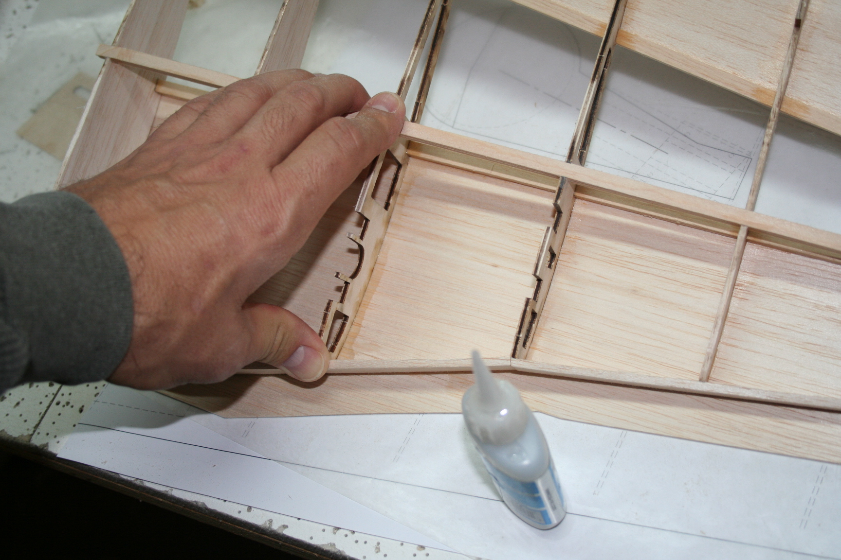
Now it is time to cut the leading edge-doublers to length.
Place them against the ribs and mark the appropriate length for each of the three angled sections. Cut them perpendicular to the building surface (at the precise angle of the ribs). Accurately determining the length of the piece running between Rib 2 - Rib 4 is particularly critical. For the strongest possible glue-joint, the length should run from the middle of Rib 2, to the middle of Rib 4, so that the other two mating LE doubler pieces can be glue to the other half of the thickness of the rib, as well as the adjacent LE doubler piece. Additionally, I beveled these LE doubler pieces where they meet at Ribs 2 and 4.
In the picture below, Tim is marking the spot at which the top of each rib (Ribs 4 - 8), at its leading edge, will contact the 1/8" x 1" leading edge-doubler. Leaving a slight margin for error when realigning and gluing in-place, cut the excess material away. This wil be less to razor-plane and sand, later.
Do the same for the two other leading edge-doubler pieces (between Rib 1 to Rib 2 and Rib 2 to Rib 4).
Last edited by Iron Dog; 12-18-2015 at 10:39 PM.
12-18-2015, 11:30 PM
#62
Thread Starter
When satisfied with the fit, glue the middle LE doubler section to ribs 2 - 4. The length measurements of the outer LE doublers aren't as critical, and they can extend beyond the outermost rib (1 or 8), Glue them into place and trim the edges close to Rib 1 at the root, and Rib 8 at the tip.
Tim left his wing pinned to the building surface and carefully razor-planed the top of the LE doubler at an angle to match that of the airfoil. Be sure to hold a little extra angle to the razor-plane to avoid catching the top of the rib and breaking or cutting it away.
I was more comfortable temporarily removing mine from the building surface, and razorplaning my wing panel's top LE "freehand."
12-18-2015, 11:54 PM
#63
Thread Starter
After planing and sanding the top surface of the LE doubler to match the contour of the airfoil on the top of the wing, I re-pinned my wing back to the building surface at the bottom spar, in preparation for the top, rear wing sheeting. (Tim will brag that by never removing his panel, he didn't have to mess with this!)
Either way, take the 3" wide 1/16th top rear and top front sheeting pieces that were prepared earlier, and trial fit them to the panel. Mark the middle of both the top 1/4" spars with a pencil or marker. Line up the rear sheeting so that the front edge extends from the rear half (1/8") of the spar to beyond the rear tips of the ribs, Run thin CA along the length of the spar to glue the sheeting down, as pictured below.


Here, Tim demonstrates gluing the top trailing edge sheeting to the midpoint of the rear spar.
Either way, take the 3" wide 1/16th top rear and top front sheeting pieces that were prepared earlier, and trial fit them to the panel. Mark the middle of both the top 1/4" spars with a pencil or marker. Line up the rear sheeting so that the front edge extends from the rear half (1/8") of the spar to beyond the rear tips of the ribs, Run thin CA along the length of the spar to glue the sheeting down, as pictured below.
Here, Tim demonstrates gluing the top trailing edge sheeting to the midpoint of the rear spar.
12-23-2015, 11:16 AM
#64
Thread Starter
After tacking the front edge of the tailing edge sheeting to the top rear spar, the wing is unpinned and turned up-side down. Thin CA is run along the rear portion of each rib, where the ribs contact the sheeting. In the picture below, note that Tim keeps the sheeting pressed against the work surface by pressing down on the rear section of each rib while applying the thin CA.

Below, Tim gives me a minor assist in gluing my top trailing edge sheeting, also -- holding my wing straight against the building surface as the glue dries.

Below, Tim gives me a minor assist in gluing my top trailing edge sheeting, also -- holding my wing straight against the building surface as the glue dries.
12-23-2015, 11:30 AM
#65
Thread Starter
The same process is carried out with the top leading edge sheeting piece:
1) Turn the wing back over again. Press it down, evenly against the building surface, and tack glue it to the front 1/8" of the top main spar.
2) Turn the wing up-side down again, and run thin CA along ribs where they contact the sheeting. I started close to the spar for each rib, applying a little CA, and "rolling" the wing forward (which lifts the trailing edge off of the table, but keeps even pressure against the curvature of the airfoil of each of the ribs and sheeting until the glue sets.
When set, I ran more thin CA along the remaining front section of each rib, rolling the panel further, and then along the leading edge doubler,
Last edited by Iron Dog; 12-23-2015 at 11:35 AM.
12-23-2015, 11:50 AM
#66
Thread Starter
Installing the main landing gear mounting rails is next. The rails are an extremely tight fit, To install them at the angle necessary, the cut-outs of the ribs must be angled by sanding them slightly. For this task, I made a thin home-made sanding bar by applying adhesive spay to the back of some sandpaper and attaching it to a 6" length of 3/16" scrap basswood.


Last edited by Iron Dog; 12-23-2015 at 03:08 PM.
12-23-2015, 12:15 PM
#67
Thread Starter
If you intend to use blindnuts, trial-fit the LG mount rails into the ribs, insert your retracts where desired, and mark the locations for the corresponding bolt holes.
Remove the rails, drill the holes squarely (in a drill press if available) then insert and glue the blindnuts.into the mounting rails. Install the retracts, then epoxy the LG mounting block/retract assemblies to the ribs.
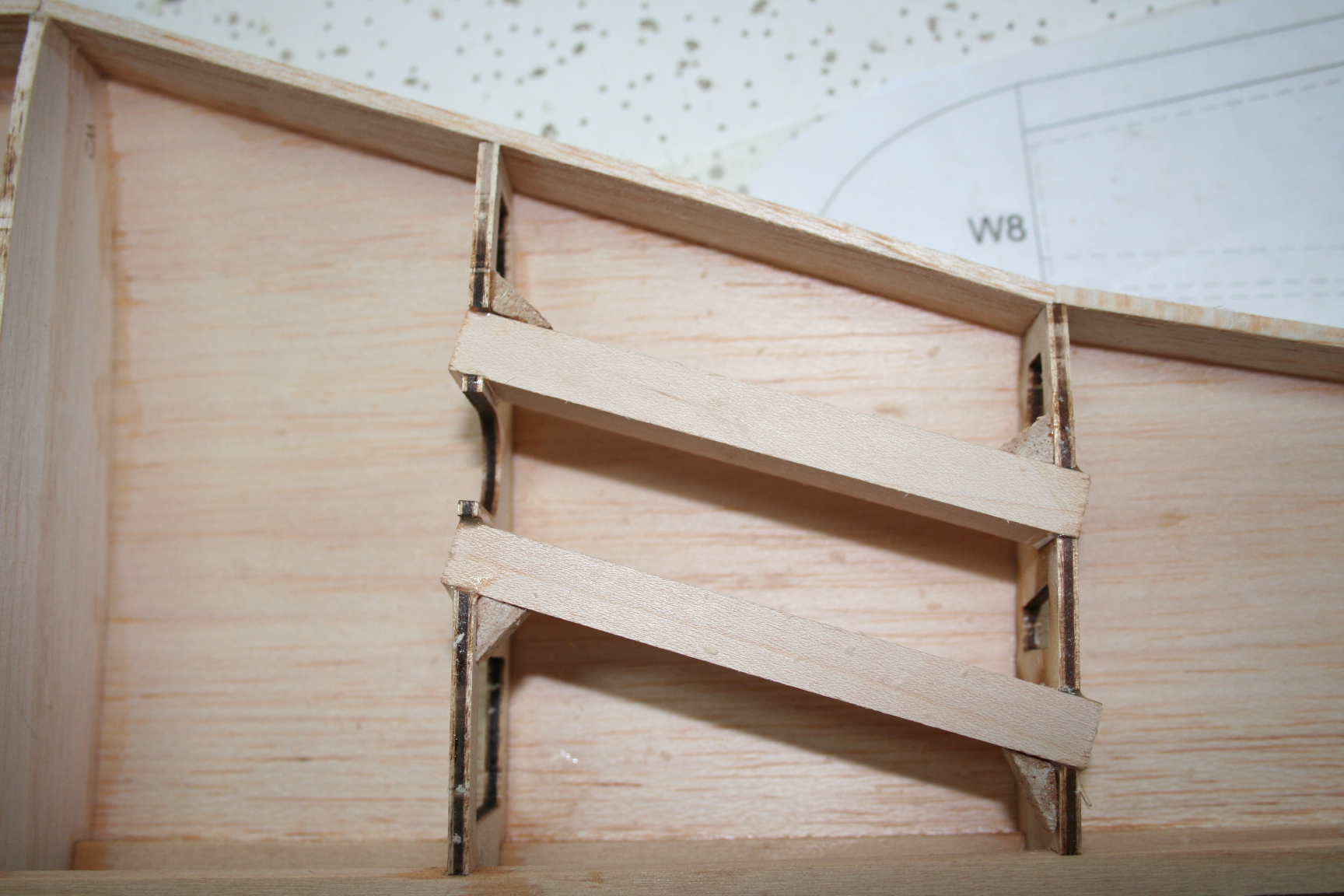
Because these mounting rails are pretty deep, Tim and I elected to skip installing blindnuts, and are simply drilling and tapping the rails for long machine screws, and will harden the threads in the blocks with thin CA. Therefore, we went ahead and epoxied our retract rails now.

I also reinforced their installation with some triangle-stock, as shown in the picture below.
Remove the rails, drill the holes squarely (in a drill press if available) then insert and glue the blindnuts.into the mounting rails. Install the retracts, then epoxy the LG mounting block/retract assemblies to the ribs.
Because these mounting rails are pretty deep, Tim and I elected to skip installing blindnuts, and are simply drilling and tapping the rails for long machine screws, and will harden the threads in the blocks with thin CA. Therefore, we went ahead and epoxied our retract rails now.
I also reinforced their installation with some triangle-stock, as shown in the picture below.
Last edited by Iron Dog; 12-23-2015 at 03:11 PM.
12-23-2015, 03:27 PM
#68
Thread Starter
Tim, Eric, and I have opted to use the HobbyKing .40-sized,electric servoless retracts with the 4mm pin. These retracts have a "hump" on the sides, right next to the mounting holes. In the picture below, I am tracing a line around the humps, and then using a Dremel with the narrow diameter sanding drum to remove just enough material from the gear mount blocks to allow the retract to clear. Be careful not to remove too much, or screws/bolts won't have as much material to "grab" into.


12-23-2015, 03:35 PM
#69
Thread Starter
Once the retract was in place, I marked my holes for the machine screws and drilled the holes with a 4-40 pilot bit, then tapped them with 4-40 tap. Tim and I recommend hardening the threads in the blocks. Apply a drop or two of thin CA, let it wick down the threads, then lightly blow any excess CA out of the blocks.


12-23-2015, 03:47 PM
#70
Thread Starter
Instead of using oleo struts, we've chosen to use basic landing gear struts and make scale LG doors. So, I removed the 4mm pins, and replaced them with Hobbico 5/32" coiled gear struts. I inserted the retract assembly into position on the blocks and traced a slightly oversized, curved line around the coil.

I then used a standard sized sanding drum in my Dremel to remove material from the mounting block in order clear the coil of the gear leg.


I then used a standard sized sanding drum in my Dremel to remove material from the mounting block in order clear the coil of the gear leg.
12-23-2015, 04:25 PM
#72
Thread Starter
We then glued in a thick, scrap block of balsa to the inside portion of the top, rear sheeting. This will fill any gaps in the area between the top and bottom rear sheeting, to keep the sheeting from getting crushed when the wing is later mounted to the fuse and the wing bolts are tightened.


The retract is removed again, in preparation of gluing in the bottom, front wing sheeting. We marked the front of the leading edge doubler with the positions of the retract mounting holes so we know where to remove sheeting from, later when inserting the retracts. For now, we wanted a solid sheet stretching across this entire surface in order to mold fiberglass gear doors that will precisely fit the landing gear bay we cut out later.
Mist the inside portion of the sheeting with CA accelerator (well away from the rest of the wing panel) and set aside. Apply medium CA on the front half of the bottom main spar, on the portion of each rib in front of this spar, and on the leading edge doubler. Do NOT apply CA to the landing gear blocks at this time. Line up the rear edge of the sheeting along the center of the main spar, then press the sheeting down against the ribs and leading edge doubler.
12-23-2015, 04:48 PM
#73
Thread Starter
Installing the shear webs is next.
Lay out the shear webs in order on either on top of the wing sheeting or on the work surface, in order. Make sure the numbering/lettering of each one is oriented the same direction.

Installing the shear webs correctly is what will "lock-in" the washout in the wing. The bottom of the wing is placed against the work surface. It is critical to ensure the washout tabs on the bottom of the wing are still in place. The most critical tabs are two outermost tabs at the root and tip of the wing. If these are accidentally broken off, new ones will need to be fabrcated before continuing.
To hold the wing down on the tabs with the appropriate "twist" to match the designed washout angles, the rear edge at the root, and the front portion at the tip must be weighted down, as Tim is pointing out in the picture below:

Being a scuba diver, I had bags of weight I pulled out of my weight belt, as well as bag of buckshot we could use, as Tim demonstrates above. If you don't have weight handy, then a friend or family member will have to firmly press the front tip and rear root sections down while the shear webs are installed.
Lay out the shear webs in order on either on top of the wing sheeting or on the work surface, in order. Make sure the numbering/lettering of each one is oriented the same direction.
Installing the shear webs correctly is what will "lock-in" the washout in the wing. The bottom of the wing is placed against the work surface. It is critical to ensure the washout tabs on the bottom of the wing are still in place. The most critical tabs are two outermost tabs at the root and tip of the wing. If these are accidentally broken off, new ones will need to be fabrcated before continuing.
To hold the wing down on the tabs with the appropriate "twist" to match the designed washout angles, the rear edge at the root, and the front portion at the tip must be weighted down, as Tim is pointing out in the picture below:
Being a scuba diver, I had bags of weight I pulled out of my weight belt, as well as bag of buckshot we could use, as Tim demonstrates above. If you don't have weight handy, then a friend or family member will have to firmly press the front tip and rear root sections down while the shear webs are installed.
12-23-2015, 05:00 PM
#74
Thread Starter
With the washout angle guaranteed, installation of the shear webs is very straightforward: Simply apply medium CA to the top and bottom of each web, one at a time, carefully line-up the top of the web with the top spar, and press them in place. Lastly, run a little thin CA to glue the sides of the webs to the ribs.


12-23-2015, 05:46 PM
#75
[QUOTE=Iron Dog;12147929]If you intend to use blindnuts, trial-fit the LG mount rails into the ribs, insert your retracts where desired, and mark the locations for the corresponding bolt holes.
Remove the rails, drill the holes squarely (in a drill press if available) then insert and glue the blindnuts.into the mounting rails. Install the retracts, then epoxy the LG mounting block/retract assemblies to the ribs.
Because these mounting rails are pretty deep, Tim and I elected to skip installing blindnuts, and are simply drilling and tapping the rails for long machine screws, and will harden the threads in the blocks with thin CA. Therefore, we went ahead and epoxied our retract rails now.
/QUOTE]
(JUST A NOTE)
I would like to point out that the gear blocks sit flush to the bottom of the outer wing rib and are recessed a little deeper on the inner wing rib. This is to insure the right 90 degree strut stance on the ground when using 85 degree retracts and the correct dihedral of 6 degrees on the bottom of the wing. In this case the 85 degree retracts are not available from Hobby King .
Last edited by tdstaf; 12-23-2015 at 05:49 PM.